Category: STEM (Science, Technology, Engineering and Mathematics)
ORIGINAL
Eliminating Inrush Current in Transformers using a Residual Flux Control Algorithm
Eliminación de la corriente de irrupción en transformadores mediante un algoritmo de control del flujo residual
Hussein A. Taha1 *, Ruaa aboalhawa1 *, Muhammad Al Badri1 *
1Department of Electrical Engineering, University of Wasit. Wasit, Iraq.
Cite as: Taha HA, Aboalhawa R, Al Badri M. Eliminating inrush current in transformers using a residual flux control algorithm. Salud, Ciencia y Tecnología - Serie de Conferencias. 2024; 3:869. https://doi.org/10.56294/sctconf2024869
Submitted: 06-02-2024 Revised: 21-04-2024 Accepted: 10-06-2024 Published: 11-06-2024
Editor:
Dr.
William Castillo-González ![]()
Note: paper presented at the 3rd Annual International Conference on Information & Sciences (AICIS’23).
ABSTRACT
Transformers in general turned on by changing the state of the circuit breakers at several times. Usually, the circuit breakers are closed at various times to turn on the transformers. This process results in high inrush currents due to the asymmetric flux produced in the coil. In light of these facts, the purpose of this study is to provide a method for controlling the switching instant that take place during the inrush of a power transformer.
The general idea is to calculate the pre-existing magnetic fluxes remaining on the base legs in terms of the three phase voltages. Then, using these data and equations, the optimal operating time is calculated to ensure that the inrush currents are reduced, and adjustment parameters are determined within the controller to obtain the least time difference between the control signals. The system was completely simulated within the MATLAB environment, and the fluxes and currents were shown without and with the controller, the results showed that the method used reduced the effect of the inrush currents with time differences of the order of milliseconds.
Keywords: Switching Control; Inrush Current; Residual Current; Transient Mitigation.
RESUMEN
En general, los transformadores se encienden cambiando el estado de los disyuntores en varios momentos. Normalmente, los disyuntores se cierran en varios momentos para encender los transformadores. Este proceso da lugar a elevadas corrientes de irrupción debido al flujo asimétrico producido en la bobina. A la luz de estos hechos, el propósito de este estudio es proporcionar un método para controlar el instante de conmutación que tiene lugar durante la irrupción de un transformador de potencia.
La idea general es calcular los flujos magnéticos preexistentes que permanecen en las patas de la base en función de las tensiones trifásicas. A continuación, utilizando estos datos y ecuaciones, se calcula el tiempo de funcionamiento óptimo para garantizar la reducción de las corrientes de irrupción, y se determinan los parámetros de ajuste dentro del controlador para obtener la menor diferencia de tiempo entre las señales de control. El sistema se simuló completamente dentro del entorno MATLAB, y se mostraron los flujos y corrientes sin y con el controlador, los resultados mostraron que el método utilizado redujo el efecto de las corrientes de irrupción con diferencias de tiempo del orden de milisegundos.
Palabras clave: Control de Conmutación; Corriente de Irrupción; Corriente Residual; Mitigación de Transitorios.
INTRODUCTION
The absence of regulation during the energization of the three phases transformers high-value currents often appea.(1) This results in transformers operating with significantly elevated saturation levels during transient situations. These high-value, asymmetric currents during the energization process are known as inrush currents. have a wide range of harmonics,(2) with both odd and even parts. It causes protective relay and fuse failure, transformer winding mechanical damage, harmonic resonance, insulation damage, and voltage sags.
The magnetizing current’s values are primarily influenced by two factors: the moment at which the switches are closed in relation to the voltage waveform and the residual flux present in the transformer’s magnetic core.(3) For instance, upon energizing the transformer, peak inrush currents might be observed due to the transient core flux reaching its highest point when the supply voltage and magnetizing current switched at the zero crossing of the voltage waveform.
On the other hand, it is feasible to begin operations immediately with the rated steady state magnetic flux in the core. This is called a direct start. Under these conditions, the steady-state magnetizing current will be assumed immediately. In order to accomplish this, the instantaneous voltages must generate equivalent fluxes in the transformer core.(4) This method avoids transient magnetization, leading the transformers directly to their ultimate steady state.
In the absence of regulated switching, energization could happen unpredictably during any point on the voltage waveform, resulting in a pronounced peak in the magnetizing current (IC) when the transformer core becomes saturated. Power transformers, being crucial elements of electric power systems, demand protective relays characterized by exceptionally reliable, secure, and swift performance. However, the presence of magnetizing current, which frequently emerges during transformer energization, has the potential to trigger erroneous trips in the differential relay. Hence, reducing the impact of IC becomes imperative.(5)
Several approaches have been devised to mitigate the effects of magnetizing current (IC). Examples of available techniques include the pre-insertion of series resistors and the synchronized closure of circuit breakers.(6)
Babaei et al.(7) introduces both a theoretical and empirical model of switched-on current, establishing the correlation between peak current and the moments of transformer switch-on and switch-off. To enhance the stability of power supply, a three-phase simultaneous closing approach is suggested, adjusting the switch-on moment based on the take-off moment. Without having to do any calculations for residual fluxes, this technique has been shown to successfully cap inrush current at 2,5 times the level of the nominal current. The authors suggest more research to determine this approach’s general applicability.
An alternative strategy for mitigating inrush current involves incorporating series resistors between neutral and ground during the transformer’s excitation phase, as detailed by Cui et al.(8). Computation and laboratory assessments have exhibited a substantial 80 to 90 % reduction in inrush current using this technique.(3,9) However, its scope is limited to star-grounded transformers and certain specialized non-grounded star circuits, rendering it inapplicable to delta circuits.
To address inrush current control in a more comprehensive manner, this study presents an approach to compute the residual flux that lingers in the transformer core following a prior turn-off event. Subsequently, a mathematical strategy is devised to identify the optimal switch-off timing for the subsequent transformer turn-on, guided by the applied voltage waveforms, thereby mitigating the undesired surge in current. Laboratory experiments provide full validation for the inrush current control methodology outlined in this work.
Strategy of inrush current mitigation
The existence of residual flux within the transformer’s core leads to an increase in the maximum inrush current during its energization process. A direct correlation is observed: higher levels of residual flux in the core correspond to elevated inrush currents resulting from the sporadic energization of the transformer.
By implementing controlled methods for energizing power transformers, a consistent reduction in inrush currents is achieved. Particularly in high voltage scenarios, the deliberate activation of circuit breakers featuring independent pole operation effectively minimizes inrush currents to an insignificant scale, thus eliminating voltage fluctuations within the grid. Similarly, in medium voltage applications, the utilization of controlled switching technology,(10) featuring simultaneous pole operation in switchgear, yields optimal mitigation of inrush currents. Although the presence of considerable residual flux within the core amplifies the inrush current observed during random energization of power transformers, the application of Controlled Switching Device (CSD) technology produces a contrary outcome. Consequently, heightened residual core flux leads to diminished energization inrush currents and, potentially, complete eradication of the same.
Determination of Residual Flux Switching
The interrelation between residual flux and transformer inrush current is substantiated through field data collected during the installation of controlled switching mechanisms in circuit breakers and switchgear with simultaneous pole operation. Across most scenarios, the employment of a CSD leads to a 3:1 reduction in inrush current compared to the arbitrary energization of transformers. The simplified equivalent electric circuit depicted in figure 1, shows as a model for describing the transformer’s behavior during the initial phase of energization.

Figure 1. Transformer single phase model
The primary phase to ground terminal voltage:
![]()
Where:
![]()
Where:
rp primary resistance
Lp primary leakage reactance
Lm the nonlinearity of the iron core’s inductance is contingent upon the magnetizing current
rsp ssecondary side resistance
Lsp leakage reactance
vp primary phase to ground terminal voltage
vs the secondary phase to ground terminal voltage respectively
θ0 is the phase of primary voltage at t =0
iφ is magnetize current
φL is core flux and N1 is number of turn in primary side
L1 is primary inductance.
By solving the two last equations:
![]()
Where Φm
is
the max of ΦL
and Φr
is residual flux.
When θ0=90
![]()
In this scenario, there exists a transient flux with a magnitude of φr and a time constant given by τ=L1/rp,. The maximum value of the magnetizing current is determined as follows:
![]()
Here, Ai represents the core’s area, At stands for the core area including windings, and µ0 denotes air permeability. The primary transient current is derived from the following equation upon connecting the transformer to the load.
![]()
Given the nominal current denoted as “I” the situation involves lsp<L1, indicating that the rapid attenuation of transient current occurs in conjunction with the load current. In this instance, IR equates to 4-6 per unit (pu).
The equation’s analysis reveals that the magnitude of the inrush current magnetizing falls within the spectrum of the SC (Short-Circuit) current. Consequently, this may lead to dynamic stress within the transformer windings, as stated by Mitra et al.(4).
Typically, the amplitude of IC does not surpass the transformer’s fault current withstand capacity. Nonetheless, the stresses persist considerably longer in duration, occurring more frequently than short circuits that are promptly cleared by relay protection within tens of milliseconds.
The magnitude of the magnetization current mainly depends on two essential factors:
· Residual flux is present in the magnetic core.
· Transient flux is generated from the integration of the sinusoidal source voltage.
When a transformer is energized precisely at the zero-crossing point of the sinusoidal voltage, both the prospective magnetizing current and the flux achieve their maximum levels, albeit with a 90-degree delay in electrical phase.
The transient flux originates from the residual flux, achieving its maximum amplitude half a period later. At this juncture, the core becomes saturated with flux, causing a substantial surge in IC current due to the core’s minimal inductance within that realm.
The angle α determines the exact time at which the switch pole must be switched to reach the optimal point on the shaft mentioned above and can be calculated according to (7):
![]()
The maximum value of the flux could be easily defined according to the relation (8):
![]()
Where:
φresidual – residual flux in the transformer legs
Vrms– RMS voltage applied to the transformer winding
n – number of turns of the excited winding
f – fundamental network frequency.
Equation 7, designed to identify the ideal switching instance for the initial phase, yield two theoretical torque values. In situations where a positive zero current is present, the switching angle falls within the range of 90° to 180°. This indicates a positive voltage with a negative rate of change. The other feasible angle ranges from 180° to 270°, indicating a negative voltage with a negative derivative. In the context of this study, the control strategy exclusively employs the first angle.
|
Table 1. Optimum point for closing two still open phases (primary: y-earth; secondary: y-earth) |
|
|
First Phase energized |
t_(optimal_closing) |
|
A |
|
|
B |
|
|
C |
|
Where:
T – Period of voltage signal
n′ – number of semi-cycles the optimal instants are repeated
The optimal switching times for phases are indicated in table 2, aligning with instances when the supply voltage reaches its peak in each phase. Consequently, these moments coincide with the presence of a suitable residual flux.
|
Table 2. Optimal switching time |
|||
|
Phase |
A |
B |
C |
|
Time of closing |
0,306 |
0,308 |
0,303 |
Modelling of Overall Proposed System
The residual flux configuration within a power transformer is a consequence of its previous de-energization.
Upon re-energizing a transformer, the dynamic flux generated by the applied voltage either adds to or subtracts from the residual flux, contingent on the polarity of the applied voltage. Based on the foundational principles of controlled switching, the most opportune instance to energize a power transformer phase is when the induced potential flux aligns with the existing residual flux.
In instances of positive flux, introducing a negative voltage gradually diminishes the core flux to zero at the nadir of the negative voltage, enabling a seamless transition to the transformer’s stable state without core saturation. Conversely, commencing phase energization at a positive zero-crossing of the voltage injects an additional 2 p.u. (per unit) of positive flux into the core, surpassing the existing 0,5 p.u. residual flux. This results in profound core saturation and a surge of inrush current. Hence, the presence of residual flux amplifies the maximum inrush current during uncontrolled transformer energization.
In scenarios where residual flux exists within the transformer core and a gang-operated circuit breaker is employed, the situation becomes even more intricate. The optimal moment for energization must account for the simultaneous activation of all three phases, taking into consideration the magnitude and direction of the residual flux. Nevertheless, for every potential residual flux configuration, there always exists an ideal point for energization that minimizes transformer saturation.
When transformer energization is not controlled, the phase with the highest residual flux invariably experiences the most significant inrush current. A controlled switching device mitigates this inrush by determining the ideal instant for pole closure based on the residual flux pattern. Consequently, specific high residual flux patterns allow for the complete elimination of inrush current.
Subsequently, the residual current can be deduced from the preceding alternating current that circulated within the core prior to the transformer being powered down. This can be accomplished by integrating the voltage applied to the transformer winding terminals. Figure 2 shows a schematic depicting the approach used to calculate the residual current within the transformer core and generate the control signals.
The data acquisition system continually captures the voltage waveform at the coil terminals during shutdown. The calculation of residual current commences from the first zero point of the voltage curve with a positive derivative, which is derived from the switch activation.

Figure 2. Controlled system block diagram

Figure 3. Flow chart of proposed control method
The method delineated earlier for computing the residual flux should also be executed by employing the zero-crossing voltage waveform featuring a negative derivative. In such an instance, the ultimate average flux value should be gauged utilizing an inverted signal.
Figure 4 shows a three-phase transformer model with random control of the breaker signals.

Figure 4. System model in MATLAB without control
The system model in MATLAB is shown in figure 5.

Figure 5. System model in MATLAB
The controller is designed to implementation the optimal timing that are described in table 1. The controller model in MATLAB is shown in figure 6.

Figure 6. Controller model in MATLAB
RESULTS AND DISCUSSION
When switching-on the transformer at random switching time or switching angle there will be high peak of inrush current appear. For switching time 0,05 the inrush current is shown in figure 7.

Figure 7. Inrush current in case of random switch
The level of residual flux present within the transformer stands as the primary factor influencing the extent of inrush current alteration. Upon the opening of circuit breakers, effectively isolating the transformer from the network, residual flux still within the transformer. Upon re-energizing the transformer, this results in an elevation of the inrush current. The residual flux is shown in figure 8.

Figure 8. Residual flux
The controller generates three control signals (control signal for each phase) and these signals are different as shown in figure 9. It’s represented the optimal switching time for all three-phases.

Figure 9. Control signals

Figure 10. Residual and core flux created by energization at zero crossing of voltage
The controller generates the optimal closing times for each phase as in table 1, the breaker current after applied the controller is shown in figure 10.

Figure 11. Breaker Current
The inrush current is shown in figure 11.

Figure 12. Inrush 3-phase current
The estimated flux mean value is shown in the figure 12 after control

Figure 13. Flux mean value
From the figure 13, it is shown that the value of the stream is reduced after applying the control algorithm. Evidently, when subjected to unregulated power-up conditions, line c has resulted in the most prominent peak for transient current. The current profiles are sufficiently lucid in accentuating the tactical efficacy of mitigating transient current spikes. In truth, the attained peak magnitudes are significantly lower than those achieved without the implementation of switching control. The magnetizing currents in the unloaded state are directly reached and absorbed by the devices.
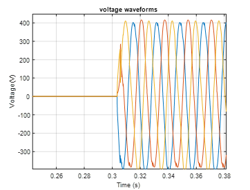
Figure 14. Measured voltage signals at the terminals of the input windings of the transformer
Figure 14 shows the measured voltage signals at the terminals of the input windings of the transformer. As mentioned earlier, phase c is the first to be turned on, followed by the other two after almost four cycles. Between these two turn-on times, it can be seen that the transformer behaves magnetically based on an induced phenomenon that can be attributed to the operation of phase c. This shows that there is a magnetic imbalance with respect to the magnetic leg flux. After the second switching, the balanced operation occurs.
The figure 15 shows the residual flux after control.

Figure 15. Residual flux after control
By comparison between figures 15 and 8, the reduction of the flux responsible for the inrush currents appears after the control, ensuring the reduction of the inrush currents. An algorithm ensures that the effect of (inrush current) is reduced 4 times in case of random switch this result is better than reference. Our paper for previous phases residual flux the maximum amplitude of the inrush current 0,75 p.u but in is approximate 3,5 p.u.
CONCLUSIONS
In this paper, a method for mitigating the inrush current of power transformers based on controlled switching was presented. In the beginning, the transformers and magnetic fluxes that are generated when the transformers work were defined. The equivalent circuit for the transformer during work was presented. Currents and flux were accurately described by mathematical equations to determine the relationship between these coefficients. An algorithm was chosen to determine the optimal time for the operation of the three-phase transformer. The parameters of the algorithm that was represented in equations of table 1 were adjusted to ensure that the effect of (inrush current) is reduced as much as possible. The time between each phase and another is short time switching for more efficient and more reliability for the network. Based on the simulation model with and without the microcontroller we obtained a fourfold reduction of effect (inrush current) for all three-phases.
BIBLIOGRAPHIC REFERENCES
1. M. Sheryar et al., “An Approach to Performing Stability Analysis for Power Transformer Differential Protection: A Case Study,” Energies, vol. 15, p. 9603, 2022, doi: 10.3390/en15249603.
2. M. Mirhosseini, “Modified park transformation of three-phase signals for harmonic extraction with frequency-adaptive capability,” International Journal of Electrical Power & Energy Systems, vol. 150, 2023. [Online]. Available: https://www.sciencedirect.com/science/article/pii/S0142061523001266.
3. Y. Pan, X. Yin, Z. Zhang, B. Liu, M. Wang, and X. Yin, “Three-Phase Transformer Inrush Current Reduction Strategy Based on Prefluxing and Controlled Switching,” IEEE Access, vol. 9, pp. 38961-38978, 2021, doi: 10.1109/ACCESS.2021.3062143.
4. J. Mitra, X. Xu, and M. Benidris, “Reduction of Three-Phase Transformer Inrush Currents Using Controlled Switching,” IEEE Transactions on Industry Applications, vol. 56, pp. 890-897, 2020, doi: 10.1109/TIA.2019.2955627.
5. B. Ge, A. de Almeida, Z. Qionglin, and W. Xiangheng, “An Equivalent Instantaneous Inductance-Based Technique for Discrimination Between Inrush Current and Internal Faults in Power Transformers,” Power Delivery, IEEE Transactions on, vol. 20, pp. 2473 - 2482, 2005, doi: 10.1109/TPWRD.2005.855443.
6. C. w. g. A3.07, “Controlled Switching of HVAC CBs: Benefits & Economic Aspects,” p. 33, 2004. CIGRE PUBLICATION.
7. Z. Babaei and M. Moradi, “Novel Method for Discrimination of Transformers Faults from Magnetizing Inrush Currents Using Wavelet Transform,” Iranian Journal of Science and Technology, Transactions of Electrical Engineering, vol. 45, 2021, doi: 10.1007/s40998-020-00399-1.
8. Y. Cui, S. Abdulsalam, S. Chen, and W. Xu, “A sequential phase energization technique for transformer inrush current reduction part 1: simulation and experimental results,” vol. 1, p. 535, 2004, doi: {10.1109/PES.2004.1372857}.
A. Yahiou, H. Mellah, and A. Bayadi, “Inrush Current Reduction by a Point-on-Wave Energization Strategy and Sequential Phase Shifting in Three-Phase Transformer,” International Journal of Engineering, Transactions B: Applications, vol. 35, pp. 1123- 1132, 2022, doi: 10.5829/IJE.2022.35.12C.07.
9. W. Chandrasena, D. Jacobson, and P. Wang, “Controlled Switching of a 1200 MVA Transformer in Manitoba,” IEEE Transactions on Power Delivery, vol. 31, 2016, doi: 10.1109/TPWRD.2016.2530631.
10. Reis, J. Oliveira, R. Apolonio, and H. Bronzeado, “A controlled switching methodology for transformer inrush current elimination: Theory and experimental validation,” Proceeding of the International Conference on Electrical Power Quality and Utilisation, EPQU, 2011, doi: 10.1109/EPQU.2011.6128821.
FINANCING
The authors did not receive financing for the development of this research.
CONFLICT OF INTEREST
The authors declare that there is no conflict of interest.
AUTHORSHIP CONTRIBUTION
Conceptualization: Hussein A. Taha, Ruaa aboalhawa, Muhammad Al Badri.
Data curation: Hussein A. Taha, Ruaa aboalhawa, Muhammad Al Badri.
Formal analysis: Hussein A. Taha, Ruaa aboalhawa, Muhammad Al Badri.
Research: Hussein A. Taha, Ruaa aboalhawa, Muhammad Al Badri.
Methodology: Hussein A. Taha, Ruaa aboalhawa, Muhammad Al Badri.
Drafting - original draft: Hussein A. Taha, Ruaa aboalhawa, Muhammad Al Badri.
Writing - proofreading and editing: Hussein A. Taha, Ruaa aboalhawa, Muhammad Al Badri.