Category: STEM (Science, Technology, Engineering and Mathematics)
ORIGINAL
The Use of Feature Technology in Selecting Cutting Tools and Generating Tool Paths
Utilización de la tecnología de características en la selección de herramientas de corte y la generación de trayectorias de herramientas
Weam A. Al-khaleeli1 *, Mohanned M. H. AL-Khafaji1 *, Mazin Al-wswasi1 *
1Department of Production Engineering and Metallurgy, The University of Technology. Iraq.
Cite as: L-khaleeli WA, AL-Khafaji MMH, Al-wswasi M. The Use of Feature Technology in Selecting Cutting Tools and Generating Tool Paths. Salud, Ciencia y Tecnología - Serie de Conferencias. 2024; 3:856. https://doi.org/10.56294/sctconf2024856
Submitted: 01-02-2024 Revised: 17-04-2024 Accepted: 10-06-2024 Published: 11-06-2024
Editor:
Dr. William Castillo-González ![]()
Note: paper presented at the 3rd Annual International Conference on Information & Sciences (AICIS’23).
ABSTRACT
Conventional manufacturing depends on the expertise of a process-planner in analyzing the design’s inputs and generating a comprehensive manufacturing plan. Despite the use of Computer Numerical Control (CNC) systems during the manufacturing process, it is still considered costly and time-consuming due to the demands of human intervention. Automation systems have become indispensable in the manufacturing industry since they significantly reduce the effort and errors of process planners, improve manufacturing flexibility, enhance efficiency, and minimize product costs. To solve the issue and achieve automation in this field, feature technology is used to automatically integrate the design and manufacturing processes. Algorithms of automatic feature recognition (AFR) have been developed to analyze geometric information of a part design, stored as a STEP file, and convert it to a set of predefined features. After completing the recognition process, a feature subtraction method is applied to solve the intersection issue of the predefined features which appears during the rough cutting cycle and generates intermediate features. This study focuses on recognizing and subtracting features of rotational parts. The system has been built via C# programing to detect set of 14 predefined final features, as well as different shapes of intermediate features. Both the final and intermediate features can be utilized to automatically generate the desired outputs of a process planning. This includes selecting machining process, sequence of operations, cutting tools and cutting conditions, and generating the G-code for machining the part. The proposed methodology has been evaluated through simulations and practical experiments, and the results were as expected.
Keywords: Process Planning; Feature Recognition; Tool Selection; Tool Path.
RESUMEN
La fabricación convencional depende de la pericia de un planificador de procesos para analizar las entradas del diseño y generar un plan de fabricación completo. A pesar del uso de sistemas de control numérico por ordenador (CNC) durante el proceso de fabricación, éste sigue considerándose costoso y lento debido a las exigencias de la intervención humana. Los sistemas de automatización se han vuelto indispensables en la industria manufacturera, ya que reducen significativamente el esfuerzo y los errores de los planificadores del proceso, mejoran la flexibilidad de la fabricación, aumentan la eficiencia y minimizan los costes del producto. Para resolver el problema y lograr la automatización en este campo, se utiliza la tecnología de rasgos para integrar automáticamente los procesos de diseño y fabricación. Se han desarrollado algoritmos de reconocimiento automático de características (AFR) para analizar la información geométrica del diseño de una pieza, almacenada como archivo STEP, y convertirla en un conjunto de características predefinidas. Una vez completado el proceso de reconocimiento, se aplica un método de sustracción de características para resolver el problema de intersección de las características predefinidas que aparece durante el ciclo de desbaste y genera características intermedias. Este estudio se centra en el reconocimiento y la sustracción de características de piezas rotacionales. El sistema se ha construido mediante programación C# para detectar un conjunto de 14 características finales predefinidas, así como diferentes formas de características intermedias. Tanto las características finales como las intermedias pueden utilizarse para generar automáticamente los resultados deseados de una planificación de procesos. Esto incluye la selección del proceso de mecanizado, la secuencia de operaciones, las herramientas de corte y las condiciones de corte, y la generación del código G para el mecanizado de la pieza. La metodología propuesta se ha evaluado mediante simulaciones y experimentos prácticos, y los resultados han sido los esperados.
Palabras clave: Planificación de Procesos: Reconocimiento de Características: Selección de Herramientas; Trayectoria de Herramientas.
INTRODUCTION
Process planning (PP) is an essential concept that links the gap between the design and manufacturing processes.(1) It transforms the raw materials via many steps into final products in accord with the designer’s vision. This requires an analysis of the inputs, such as the geometrical and topological information of the design, and knowledge about the available resources, including machine tools, work-holding devices, and cutting tools. Regarding the outputs, process planning can specify an operation sequence, determine machining parameters (i.e., cutting speed, feed rate, depth of cut), and generate a tool path.(2,3) Whilst process planning is one of the most important aspects of the production process, it depends on the experiences and knowledge of the planners. Consequently, this may affect the product’s quality, consume time, lead to losing the manufacturing feedback, expend process sheets, create a gap among planning experts, and result insufficient planning outputs. These consequences, as well as the reduction in the number of experienced process planners in industry, encouraged to develop efficient techniques to minimize expected errors and time.(1,2,4)
Since about seven decades ago, computers have been used to aid process planners in their planning functions, and the concept of computer-aided process planning (CAPP) was established. The use of computers is not limited to aid PP tasks, for it is also used with the design and manufacturing processes.(5) Hence, different CAPP techniques have been developed to connect the computer-aided design (CAD) and the computeraided manufacturing (CAM) systems.(6,7) However, the use of computers in achieving process planning activities does not necessarily mean that they are being accomplished automatically. Therefore, a new version of CAPP is required to achieve the related tasks in an accurate, fast, and robust way with minimum human intervention.
Recently, the form of automatic computer-aided process planning (ACAPP) has appeared and replaced the previous versions. Different tools, concepts and techniques are used to support the success of the ACAPP system. The use of feature technology is the first and most important step to any ACAPP system. A feature is a part’s characteristics that is essential for a particular application. The feature technology includes two main parts: automatic feature recognition (AFR) and features subtraction. The main idea of AFR is to automate the transfer of component description data from a CAD system to information that can be used in the process planning phase.(3,8,9) This is because CAD models provide lower-level information, such as faces, planes, edges, and vertices; whereas PP accept high-level features, such as grooves, steps, and taper.(10) This process starts with saving the design as a file that the recognition system can accept as input. The file can take any format of the international product data exchange (PDE) standards, such as drawing exchange format (DXF), initial graphics exchange specification (IGES), or standard for external representation of Product Model Data (STEP) files.(11,12) However, special attention has been paid to the STEP file because it transfers both geometrical and topological information of the design.(13) The second phase of the features technology is the features subtraction. This is when two or more adjacent final features intersect and form intermediate features. Both the final and intermediate features are used in the ACAPP system and help in generating the expected outputs.
Tseng et al.(14) proposed the machining volume generation (MVG) method. The volume of each feature is found by sweeping the boundary faces along a direction that is specified based on the type of machining operation. This includes both rotational and prismatic features for turning and milling machining, respectively. The developed algorithms are utilized by employing the 3-D boundary representation, which is based on the ACIS solid modeling system. Mangesh et al.(15) developed a feature extraction system based on the principles of object oriented modeling and C++ programming language. It takes the STEP AP 202 file as an input comprised of the geometry and topology data of the part. This system was developed for solids which can be manufactured by milling process. However, the authors mentioned it can be expanded to extract features from turned parts as well.
Derek et al.(16) proposed a decomposition method that assists process planners by creating a data structure to recognize specific 2-D patterns for turned components. This data structure allows for easy searching of patterns, whether they are common or customized by the user. According to the authors, the developed algorithms can be adapted to include parts with complex curved boundaries and parts that are machined from near-net-shape workpieces. Al-wswasi et al.(17) offered a novel and smart interactive AFR (SI-AFR) approach for recognizing rotational features using one of the STEP AP203, AP214, or AP242 files as an input. Whilst the system is able to recognize 54 predefined final features, it has the ability to automatically analyze new features and add them to its database. Later, they published a study based on the concept of features subtraction to solve the intersection issues of manufacturing features. Such a system has the ability to define and split the volumes that should be removed during the rough cutting.(18)
In this research, the issue of developing an automatic system that generates CAPP outputs using both the AFR and feature subtraction concepts has been considered. This involves an automatic analysis to introduce a full description for each final and intermediate feature. Furthermore, the system automatically selects the machining processes, finds the sequence of operations, specifies the cutting tools and cutting conditions, and finally generates the G-code for machining the part.
Unraveling Geometrical and Topological Insights through STEP File Analysis
As mentioned, the STEP file is one of the PDE standards which are utilized for sharing and transforming engineering data between various computer-aided systems.(8,13,19) The STEP file is a language-based document that contains strings and digits which describe a product’s representation. Whilst different Application Protocols (APs) have been created to serve many industrial applications, most of these utilize the EXPRESS language for data description. This work uses the AP 203 STEP file since it meets industrial needs for individual mechanical parts or assemblies. The structure of AP 203 is divided into two main sections: ”HEADER” and ”DATA”.
The HEADER section includes non-geometrical information, such as the designer, file, and company name, as well as the creation date. Whereas the DATA section provides all the geometrical and topological information of the part in terms of lines of entities. Each line starts with ”#” mark followed by a unique integer and contains the name of the entity along with other product-related information. The geometrical and topological information of the AP 203 STEP file is arranged in a hierarchical shape. Whilst the ”CLOSED SHELL” describes the product as a region in 3D space and represents the top of the hierarchy, it does not necessarily appear at the first line of the STEP file. In fact, it can take any order at the entire DATA section. This is not limited to the top level of the CLOSED SHELL since it holds true for all other levels of the data.
The faces are the second level of the STEP file hierarchy. A face can take different possibilities of shapes, such as plane, cylindrical, or conical, and is bounded by loops of edges. Each two adjacent faces share one edge; consequently, the sum of the faces form the shell of the product. Depending on the case, the face line might contain two or more entities. The two digits refer to the face outer bound and type of the face; whereas each additional digit denotes the existence of an internal face bound.
Regardless of the type, both the outer and internal bounds entities include an ”EDGE LOOP” indicator, which is a closed path of connected oriented-edges. Each “ORIENTED EDGE” denotes to one “EDGE CURVE” entity representing a border with a defined start and end point. The “EDGE CURVE”, in turn, has a complete geometrical and topological definition, and this depends on the type of edge. For example, a line can be defined via its start and end points, vector, and one direction. On the other hand, a circle is characterized by a start, end, and center points, along with a radius and two directions. The lowest level in the STEP hierarchy is the Cartesian points, where each one defines a vertex in Cartesian space in terms of x, y, and z axes of the hierarchy. Hence, the geometrical and topological information are difficult to follow since they require moving from one line to another in a non-sequential way. This can be time-consuming, inaccurate, and confusing not only for humans but also during the preparatory stages of the feature recognition process. This is the first step of the proposed system where an original AP 203 STEP file is imported to be reorganized and interpreted. For this purpose, many “Classes” have been developed via C# programming code. Each Class represents a specific level of entities, and they are all interconnected within the same hierarchical design. Although the process of reorganizing and interpreting an imported STEP file presents its information sequentially, more processing and editing are required before progressing to the feature recognition step.
Analyzing and Editing the STEP File
Numerous algorithms have been created in this research to analyze and edit the reorganized STEP file. This is to facilitate and support the next phase of feature recognition, by presenting the part’s information in a more convenience way:
Finding Effective Values for Faces
The first algorithm aims to determine the maximum and minimum Z and X values for each face of the part. This is achieved by scanning all the Cartesian points which are involved in each edge of the face. However, the extracted values may vary depending on the type of the face. For example, the part in figure 1 has two types of planes, cylindrical, and conical faces. Whilst both the cylinder and conical faces have different maximum and minimum Z values for the start and the end points, each of the planes have the same maximum and minimum Z values. Also, the X start value of the cylinder is equal the X end value, in contrast with the conical that has two different values of X for the start and the end. Moreover, plane 1 has only an outer bound of edges, whereas plane 2 includes outer and inner bounds which require extra scanning to determine the X values.
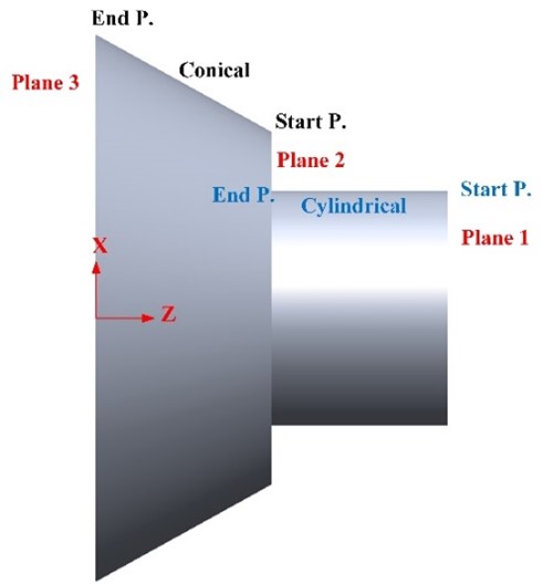
Figure 1. Finding effective X and Z values for faces
Resorting the Faces
Although the STEP file has been reorganized and the information of each face up to this point appears sequentially, this does not change the fact that the overall faces are not sorted logically. Since this project adopts the rotational parts, which are manufactured on turning machines, a sorting algorithm has been developed for the purpose of delivering a convenience order of faces to the feature recognition phase. In this example, the order of faces will be (plane 1, cylindrical, plane 2, conical, plane 3).
Removing the Duplicate Faces
The symmetrical rotational faces, such as cylindrical and conical, require a special consideration. This is because each of them appears as a single face in any CAD model; however, they are represented as two separated faces in the structure of the STEP file. For example, a cylinder in has two circular faces on the sides and one cylindrical surface linking them. Regarding the STEP file, this cylinder is saved as four faces of two circular faces and two halves of the cylindrical surface. This might confuse the feature recognizer and lead to uncertain results. Thus, the system merges the information of every two symmetrical faces to be read as one face.
Features Technique
Each part design or product consists of features; however, the number and nature of features depends on the part complexity. These features describe the part‘s attributes and enhance the interaction between the design and manufacturing processes. The two main aspects of implying the features technique are: automated feature recognition (AFR) and features subtraction. Whilst the former transfers the low-level information of the design to high ones of final manufacturing features, the later assists in dividing the volume that should be removed into blocks. The next sections illustrate the approaches and methodology of each aspect.
Automated Feature Recognition
As mentioned, the concept of automatic feature recognition (AFR) plays an essential role in the automation of process planning. The proposed AFR system adopts the “Rule-based“ technique, which is an advanced version of the syntactic pattern method. This is due to its ability in recognizing complex 3D rotational parts. However, the type and number of features should be specified before building the system.
Predefined Features
The process of developing an AFR system always starts with specifying a group of target features. These are geometrically and topologically defined and saved via programming code in a structured way within the system. They are referred to as ”Predefined Features“ and used as references each time a process of feature recognition is run. In this research, a set of fourteen predefined features has been selected. They are categorized into groups based on the number of faces involved in creating them.
Methodology of Recognition
After reorganizing and editing the STEP AP 203 file, it is imported to the system as an input. Since the proposed system has been developed using the rule-based approach, each feature in the part will be recognized by scanning the faces and matching them with the saved predefined features, following certain rules that are characteristic to that feature. The process of scanning the faces involves loops designed based on the selected set of predefined features. The set includes five groups of features, classified by the number of faces they involve in forming each one. These have a range from one face to a maximum of five faces. Hence, the scanning starts with holding the first five faces of the STEP file and searches for a matching. If a match is found, the first loop terminates, and the system declares that these five faces form a final feature. The system also extracts all the geometrical data and represents them in a compatible way with the recognized feature. Then, the second loop starts and this time the next five faces (F6 to F10) are considered. However, if no matching is found, the first loop continues by subtracting the fifth face and keep only the first fourth ones. This time the system seeks for a matching in the group that comprises features with four faces. Such a procedure guarantees accurate results by giving priority to the complex features that contains a higher number of faces. Also, it makes sure that all the faces have been covered and each of them belongs to a certain final feature.
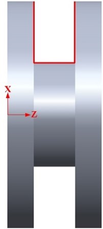
It is very important to note that each predefined feature is unique in terms of description. Hence, the developed rules of recognition must be highly accurate to prevent errors. For example, the parts in figure 2 a and b have the same sequence of faces (plane, cylindrical, and plane) as they appear in red lines. Whilst this sequence of faces represents a square groove feature in figure 2 a, they do not form the same feature in the case of figure 2 b. Thus, the ARF system puts in consideration all the necessary geometrical and topological information to avoid such misinterpretations.

(a) (b)
Figure 2. Three Faces Configured as (a) Square Groove and (b) Right Step
Although the proposed AFR system has the ability to define all the designed faces and turn them into manufacturing final features, this does not change the fact that intersecting issues will appear in most “if not” all the cases during the manufacturing phase. This requires a deep investigation regarding this challenge and a reasonable solution to avoid it. The next section explains this matter in detail and presents a methodology to sort it out.
Feature Subtraction
Material cutting can be defined as a subtractive process that forms feature surfaces by removing one or more layers of the workpiece. These layers can take several shapes and vary in their complexity due to the intersecting of the final features. Specifying the geometrical and topological boundaries of the removed layers is crucial for identifying most CAPP outputs. For example, it affects the selection of the cutting tools and generating the cutting path. However, the process of determining the layers boundaries does not follow a specific rule, and it can be achieved through various strategies. In order to find a practical and reasonable solution, this requires deep knowledge about the issue of intersecting features.
Defining the Issue
The intersection of features is an inevitably issue in most, if not all, material cutting processes. The proposed AFR system can solve a simple level of this issue. However, this is not as straightforward as it may seem in the case of figure 3 a. The AFR system declares the existence of seven features, these are from right to left (facing, cylindrical, left step, wide radial groove, right step, cylindrical, and facing). Whilst the intersection between these features is obvious, the division strategies require deep vision and analysis to select to ideal possibility. In this example, both figure 3 b and c are considered impractical solutions and might damaging a feature and interrupting the movement of the cutting tool. Figure 3 d is the most convenient division of the intersected area since it decreases the tool path in an efficient manner that helps machining one or more feature in a direct and indirect way. However, this is only one case of intersection with few suggestions of divisions. Complex designs might generate more prospects, consequently, an efficient methodology of subtraction should be developed to cover such cases.
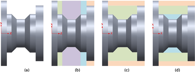
Figure 3. (a) A design model and (b), (c), and (d) three different strategies of dividing the machining volume
Methodology of Subtraction
The final shape of the product can be described as a set of final features recognized from the AFR phase. These final features interact during the manufacturing process, resulting in one or more volumes of “intermediate features” that need to be removed from the workpiece. This statement holds the truth for all the cases since the initial stock is a blank cylinder and requires several passes of cutting to reach the final shape. As mentioned, there are several possibilities to divide the volumes and getting the intermediate features, and these vary between impractical, acceptable, and optimal divisions. This section presents a methodology of intermediate features calculation or subtraction via several steps.
Step one: involves scanning all the final features and checking the faces that constitute each one. This is to find all the X values of the start and end points and determine the maximum among them. Depending on the case, the maximum X value may belong to one or more final features. Figure 4 shows a case when the maximum X exists on three connected final features (right step, cylindrical, and facing).
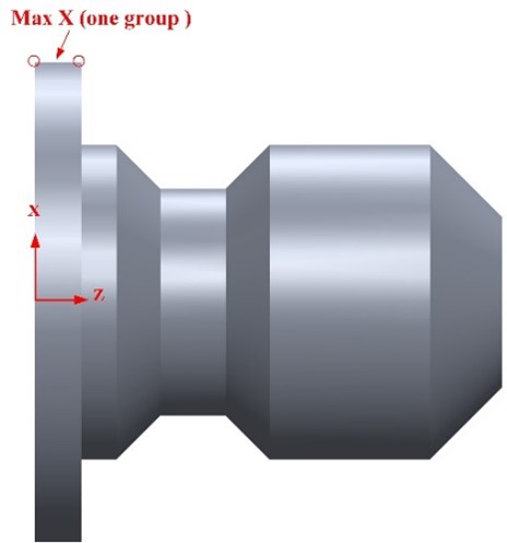
Figure 4. An example of which points are taken as maximum X
Step two: after determining the maximum X value and identifying the features with it, this step examines whether these features are connected to each other or not. This is by checking if a feature from the observed group shares an edge with its peers. Then, all the connected features are grouped together. For example, the part in figure 4 has only one group of final features that share the same maximum X; whereas, the part in figure 5 includes two groups of features sharing the same maximum X.
Step three: all the groups from the previous step are examined. This is by applying the same procedure to each final feature within these groups. In this stage, the system takes the created groupings of features one by one. The feature is taken as a reference and the final features on its right side are scanned. The scanning starts from the first neighbor and stops if one of two conditions is met. The first condition is realized if the scanning process reaches a feature with an equal or greater observed X value. For example, when the “right step” from “group2” in figure 5 is taken as a reference and scanning its right side, the scanning will stop when it reaches to the “left step” of “group1”. In such a case, the result of the scanning process will be (right step, wide radial groove, and left step). The second condition is met when the scanning reaches the far right side without encountering any features, as in the first case. Figure 4 illustrates this condition when taking the “right step” as a reference and scanning its right side. The result is (right step, wide radial groove, cylindrical, right taper, and facing). Next, the procedure is repeated to the same feature and conditions, but with scanning its left side. All the results from the scanning processes are held for the next step. However, if the scanning stops directly on the right and left sides, the observed feature is recorded as an “independent final feature”.
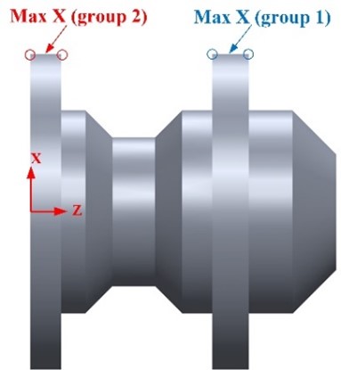
Figure 5. Two groups of features have the same maximum X value
Step four: each group of features from step three contains a referenced feature and others that resulted from the scanning process. Hence, there is at least one feature that holds the observed maximum X value. The system now checks all the X values at this group of features to find the second maximum X. Depending on the case, the second maximum X value may belong to the referenced feature or any other one. Figure 6 a and b shows two different cases when the second maximum X is located at the observed feature and another one, respectively.

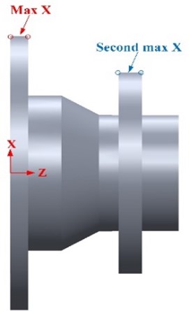
(a) (b)
Figure 6. (a) and (b) Two different examples where the second highest X value can be
Step five: the concept of feature subtraction aims to address intersection issues by dividing the extra zone of the blank into volumes and removing them in a logical sequence. These volumes represent either independent final features, such as square and wide grooves, or intermediate features. Whilst the boundaries of the final feature are fully defined using the proposed AFR system, the intermediate ones require a different methodology to be recognized. The first four steps prepared all the necessary information to draw the boundaries of the intermediate features. In fact, this task depends on two factors. These are the first and last features of each bundle from step three and the value of the second maximum X from the fourth phase. However, the design of the part influences the utilization of the mentioned factors. For example, scanning the right side of the “right step” feature in figure 4 results (right step, wide radial groove, cylindrical, right taper, and facing). In order to draw the first boundary of the intermediate feature, consider the feature on the far right side, which in this case is “facing”. Next, the third face is found to facilitate the calculation of the second face. This time the far left feature, which in this case is “right step”, is utilized to draw the third face of the intermediate feature. However, the same logic and X value comparison process are applied.
Regarding the second face of the intermediate feature, it only requires drawing a horizontal line connecting between the end point of the first face and the start point of the third face. This statement holds true for all the cases regardless of the shape of the first and last features in (step three). Figure 7 shows the start and end points of the three faces of the intermediate feature.
Figure 6b provides another example illustrating the impact of the second maximum X location. While the logic and rules for the first face remain the same as in the previous case, the rules for the third face are adjusted to match the specific instance. The three faces of the intermediate feature are illustrated in figure 8. However, there are many other cases that the system can solve in a logical way.
Step six: depending on the complexity of the design, the same procedure from step 1 to step 5 might be repeated as loops if required. This will stop when all the final features and the intersecting volume between them are covered. Hence, the whole part will be divided into zones of independent final features and intermediate ones. Such a division facilitates the development of an automatic CAPP system. Precisely, it plays an important role in the tasks of selecting the cutting tools or each final and intermediate feature and generating the tool path.
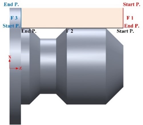
Figure 7. The start and end points of the three faces of the intermediate feature
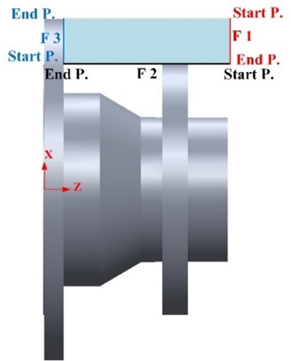
Figure 8. The start and end points of the three faces of the intermediate feature
Tool Selection and Tool Path
The main purpose of this research is to automatically generate some of the CAPP outcomes, such as the tool selection and too path. This can be achieved using the rich geometrical and topological information from the AFR and features subtraction phases. To achieve the tool selection task, two main factors must be considered: the location and geometry of features. Regarding the location of the feature, consider the example of “facing” to illustrate the necessity of knowing its location. If the design has a facing on its both sides, a tool with an insert of 80°-point angle is selected for cutting the right side; whereas, a special square parting tool is chosen for the left side. The geometry of the feature on the other side can also influence the process of selection. This applies especially to various types of grooves and intermediate features, as well as right and left tapers. For example, the system selects a tool with a square section not only for cutting square grooves but also for intermediate features with vertical boundaries on both sides, located in the middle of the part.
Since the task of tool selection is accomplished automatically, the system is able now to generate a tool cutting path. An algorithm and a set of rules have been developed for this purpose. This is achieved based on several factors, such as geometrical and topological data of all the features, their location, and the size and geometry of the cutting tool. The tool path is automatically generated, giving priority to features on the circumference before moving to the core of the workpiece. This is to prevent any damage to the workpiece and the tool. Also, the system aims to avoid unnecessary changing tools whenever possible to reduce the whole machining time and cost.
Case Study
The proposed system includes many phases starting from importing a part design as a STEP AP 203, reorganizing and manipulating the file, recognizing the final features via AFR rules, applying the concept of feature subtraction, and finally selecting a set of cutting tools and generating a tool path in an automatic way. All the necessary algorithms have been developed and implemented using C# programming. The part design in figure 9 is considered for the purpose of tracking and evaluating each phase of the system. Firstly, the part is designed using SOLIDWORKS software and saved as a STEP AP 203. Next, the system imports the file and reorganizes its information in a reasonable way for both the computer and the user. However, it shows that the original file consists fifteen disordered faces. These faces are manipulated using various algorithms, resulting in ten faces arranged from right to left: plane, cylindrical, plane, conical, cylindrical, plane, cylindrical, plane, cylindrical, and plane. Such preparation facilitates the task of feature recognition. The next step includes applying the AFR rules to convert the low-level data of the design into a higher-level that can be used in manufacturing. The AFR phase recognizes seven final features and retrieves their essential data. However, these describe the final shape of the part and are useful during the finish cutting cycle.
Since the initial stock is a blank cylinder, it requires a rough cutting process to approximate the final shape. This phase involves the removal of most of the excess material. The shape and volume of the remaining material are primarily determined by the intersections of the final features. Therefore, it should be subdivided into zones based on intermediate features in a logical manner to facilitate the cutting process and minimize the risk of damaging the part. The features subtracting phase analyzes the final features and denotes the existence of an intermediate feature besides independent final ones, as shown in table 1.
The last two steps are the automatic selection of the cutting tools and the generating of the tool path. Regarding the former, the system selects a set of tools from its inner database based on the geometry and location of each intermediate or final feature. In this case study, three different tools have been selected automatically to cover all the required rough cutting. A tool with an insert of 80°-point angle cuts the intermediate feature, right step, and the facing, as well as the two cylindrical. Whereas a tool with a square section and of 4 mm width is chosen for the square groove. Finally, a special parting tool with 3 mm width is automatically selected and used for cutting off the part. Also, the recognition and sorting of the features as in table 1, along with information about the cutting tools, play a crucial role in the automatic generation of the tool path in terms of G code. Depending on the geometrical data and the location of each feature, the system may use simple function such as G1 or a canned cycle like G71, G72, and G75. Figure 9 clarifies the sequential machining process of the entire part, with each step represents one feature. In order to evaluate the system, both simulation and practical work have been executed. The CNC Simulator Pro software is employed in the simulation to assess whether the tool geometry and the generated G code could produce the final part shape accurately. Based on the result, the simulated part is very accurate in terms of shape and dimensions. Figure 10 shows screen shots of two modes during the simulation process. Regarding the practical work, an experiment has been carried out at the University of Technology - Iraq workshop. This is by machining a stock of Polytetrafluoroethylene (PTFE) on Knuth StarChip 450 lathe machine. The final part has been measured, and the results match the expected outcome. Figure 11 shows the final machined part.
|
Table 1. The results from the features subtracting phase |
|||
|
|
Feature Name |
No. faces |
Details |
|
1
|
Intermediate Feature
|
3
|
Face No.1 First Point: X =22, Z = 47 Second Point: X =17, Z = 47 |
|
Face No.2 First Point: X =17, Z = 47 Second Point: X =17, z = 32 |
|||
|
Face No.3 First Point: X =17, Z = 32 Second Point: X =22, Z= 25 |
|||
|
2 |
Right Step
|
2
|
Face No.1 First Point: X =13, Z = 47 Second Point: X =13, Z = 32 |
|
Face No.2 First Point: X =13, Z = 32 Second Point: X =17, z = 32 |
|||
|
3 |
Facing
|
1
|
Face No.1 First Point: X =0, Z = 47 Second Point: X =13, Z = 47 |
|
4 |
Cylindrical
|
1
|
Face No.1 First Point: X =22, Z =25 Second Point: X =22, Z = 17 |
|
5
|
Neutral Square Groove
|
3
|
Face No.1 First Point: X =22, Z = 17 Second Point: X =16, Z = 17 |
|
Face No.2 First Point: X =16, Z = 17 Second Point: X =16, Z = 10 |
|||
|
Face No.3 First Point: X =16, Z = 10 Second Point: X =22, Z= 10 |
|||
|
6 |
Cylindrical
|
1
|
Face No.1 First Point: X =22, Z= 10 Second Point: X =22, Z = 0 |
|
7 |
Facing
|
1
|
Face No.1 First Point: X =22, Z = 0 Second Point: X =0, Z = 0 |
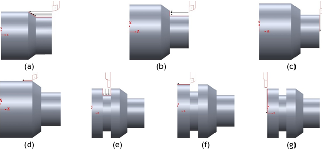
Figure 9. The sequence of the cutting paths
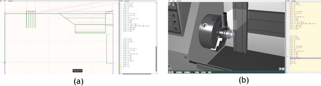
Figure 10. (a) Simulation’s window in 2D, and (b) Simulation’s window in 3D

Figure 11. The final machined part
DISCUSSION
In this research, a proposed system has been developed via many phases to fill the gap between CAD and CAPP systems. It starts with importing a STEP AP 203 file and parsing it to reorganize the information for better clarity. Three algorithms are employed to analyze and edit the STEP file, enhancing the efficiency of the feature technology workflow. The phase of feature technology includes two main sectors: AFR and features subtracting. Despite their differences in nature, both sectors share the common goal of bridging the gap between CAD and CAPP systems. AFR plays a crucial role in this phase by transforming basic geometric shapes, such as lines and arcs, into distinct manufacturing features. Examples of these features include square grooves, wide grooves, and right and left steps. This is achieved by constructing a database of fourteen predefined features and employing loops to identify the final features of the part. The features are fully defined in terms of geometrical and topological information. However, one or more intersections occur during the manufacturing process. Different strategies can be proposed to resolve situations where features intersect based on the part design and the process planner vision. The evaluation of these proposed solutions might be unreliable, acceptable, or optimal, depending on the specific context and requirements.
The features subtracting phase suggests a methodology of six steps that guarantees covering all the excess material and dividing it into intermediate and independent features. The final phase of the system involves the automatic selection of cutting tools and the generation of the tool path. While CAM software is commonly used to assist in these tasks, they often rely on user experience for specifying cutting zones, selecting appropriate tools, and defining cutting strategies. In contrast, the proposed method relies on a deep analysis of the geometry and location of each feature to achieve these tasks automatically. This approach reduces the need for extensive user experience, avoids damaging the part and the tool, and decreases the manufacturing time and cost.
However, this is only one aspect of a larger project that aims to accomplish not only automatic generating of CAPP outputs, for it also intends to achieve automatic machine setup. The future work can be expanded to:
· Include prismatic parts and milling process features.
· Incorporate both feature technology and image processing for this purpose.
BIBLIOGRAPHIC REFERENCES
1. G. Schuh, J. P. Prote, M. Luckert, and P. H¨unnekes, “Knowledge discovery approach for automated process planning,” vol. 63. Elsevier B.V., 2017, pp. 539–544.
2. J. Oussama, E. M. Abdelilah, and R. Ahmed, “Manufacturing computer aided process planning for rotational parts. part 2: A new approach for optimizing multiple interpretations of interacting features based on manufacturing rules and metal removal principals,” International Journal of Innovation and Applied Studies, vol. 8, 2014.
3. A. Oral and M. C. Cakir, “Automated cutting tool selection and cutting tool sequence optimisation for rotational parts,” Robotics and ComputerIntegrated Manufacturing, vol. 20, pp. 127–141, 4 2004.
4. O. Jaider, A. E. Mesbahi, H. Zarkti, A. Rechia, and A. E. Mesbahi, “An automatic feature-based cutting tool selection approach for turning process,” International Journal of Current Engineering and Technology, vol. 5, 2015. Online.. Available: http://inpressco.com/category/ijcet
5. V. E. Lelyukhin, O. V. Kolesnikova, and K. N. Permyakova, “Geometry problems in formalizing the creation of machining processes on machine tools,” Digital Manufacturing Technology, pp. 91– 105, 8 2023.
6. Y. Yusof and K. Latif, “Survey on computer-aided process planning,” International Journal of Advanced Manufacturing Technology, vol. 75, pp. 77– 89, 10 2014.
7. M. Al-wswasi, A. Ivanov, and H. Makatsoris, “A survey on smart automated computer-aided process planning (acapp) techniques,” International Journal of Advanced Manufacturing Technology, vol. 97, pp. 809–832, 7 2018.
8. V. V. Rampur and S. Reur, “Computer aided process planning using step neutral file for automotive parts,” International Journal of Engineering Research & Technology (IJERT), vol. 6, 2017. Online.. Available: www.ijert.org
9. N. Ismail, N. A. Bakar, and A. H. Juri, “Recognition of cylindrical and conical features using edge boundary classification,” International Journal of Machine Tools and Manufacture, vol. 45, pp. 649– 655, 5 2005.
10. B. Venu and V. R. Komma, “Step-based feature recognition from solid models having non-planar surfaces,” International Journal of Computer Integrated Manufacturing, vol. 30, pp. 1011–1028, 10 2017.
11. D. Sreeramulu and C. Rao, “A new methodology for recognizing features in rotational parts using step data exchange standard,” International Journal of Engineering, Science and Technology, vol. 3, pp. 102–115, 1 1970.
12. J. Gao, D. T. Zheng, N. Gindy, and D. Clark, “Extraction/conversion of geometric dimensions and tolerances for machining features,” International Journal of Advanced Manufacturing Technology, vol. 26, pp. 405–414, 8 2005.
13. D. Sreeramulu, N. Ramesh, C. J. Rao, and A. Professor, “Integration of computer aided design and computer aided manufacturing using step data exchange standard.”
14. Y. J. Tseng and S. B. Joshi, “Recognition of interacting rotational and prismatic machining features from 3-d mill-turn parts,” International Journal of Production Research, vol. 36, pp. 3147–3165, 1998.
15. M. P. Bhandarkar and R. Nagi, “Step-based feature extraction from step geometry for agile manufacturing,” Computers in Industry, vol. 41, pp. 3–24, 2000. Online.. Available: www.elsevier.nlrlocatercompind
16. D. Yip-Hoi, D. Dutta, and Z. Huang, “A customizable machining feature extraction methodology for turned components,” journal of Manufacturing Systems, 2003.
17. M. Al-wswasi and A. Ivanov, “A novel and smart interactive feature recognition system for rotational parts using a step file,” International Journal of Advanced Manufacturing Technology, vol. 104, pp. 261–284, 9 2019.
18. “A features subtraction system for rotational parts based on manufacturing and metal removing concepts,” International Journal of Advanced Manufacturing Technology, vol. 107, pp. 1835–1857, 3 2020.
19. B. R. Borkar and Y. M. Puri, “Automatic extraction of machining features from prismatic parts using step for downstream applications,” Journal of The Institution of Engineers (India): Series C, vol. 96, pp. 231–243, 7 2015
FINANCING
There is no specific funding to support this research.
CONFLICT OF INTEREST
All authors reviewed the results, approved the final version of the manuscript and agreed to publish it.
AUTHORSHIP CONTRIBUTION
Conceptualization: Weam A. Al-khaleeli, Mohanned M. H. AL-Khafaji, Mazin Al-wswasi.
Data curation: Weam A. Al-khaleeli, Mohanned M. H. AL-Khafaji, Mazin Al-wswasi
Formal analysis: Weam A. Al-khaleeli, Mohanned M. H. AL-Khafaji, Mazin Al-wswasi
Research: Weam A. Al-khaleeli, Mohanned M. H. AL-Khafaji, Mazin Al-wswasi
Methodology: Weam A. Al-khaleeli, Mohanned M. H. AL-Khafaji, Mazin Al-wswasi
Drafting - original draft: Weam A. Al-khaleeli, Mohanned M. H. AL-Khafaji, Mazin Al-wswasi
Writing - proofreading and editing: Weam A. Al-khaleeli, Mohanned M. H. AL-Khafaji, Mazin Al-wswasi