Category: STEM (Science, Technology, Engineering and Mathematics)
ORIGINAL
Simulation and Experimental Approach for Metal Forming with a Multi-Point Die
Simulación y enfoque experimental para el conformado de metales con una matriz multipunto
Alyaa Al-Ghuraibawi1 *, Aseel Hamad Abed1 *, Khalida Kadhim Mansor1 *
1Department of Production Engineering and Metallurgy, The University of Technology. Iraq.
Cite as: Al-Ghuraibawi A, Hamad Abed A, Kadhim Mansor K. Simulation and Experimental Approach for Metal Forming with a Multi-Point Die. Salud, Ciencia y Tecnología - Serie de Conferencias. 2024; 3:855. https://doi.org/10.56294/sctconf2024855
Submitted: 01-02-2024 Revised: 16-04-2024 Accepted: 04-06-2024 Published: 05-06-2024
Editor:
Dr.
William Castillo-González ![]()
Note: paper presented at the 3rd Annual International Conference on Information & Sciences (AICIS’23).
ABSTRACT
Multi-point forming (MPF) is considered a flexible and innovative sheet metal forming process that allows for the creation of three-dimensional curved surfaces. This study investigates the effects of various parameters on the final product in metal forming using a multi-point die. The research employs a combination of numerical simulations and experimental work to analyze and minimize defects in the forming process. The concentration is on brass (Cu Zn 65-35) and rubber materials, with specific thicknesses of 0,71 mm and 2 mm, respectively. Although ANSYS 15.0 is used to study the stresses and strains resulting from the formation process with the multi-point die (MPD), the experimental work was conducted to study the effect of two parameters: forming speeds (5 and 15 mm/min) and holding times (1, 3, and 5 minutes were used in this process). The simulation results reveal that the use of rubber significantly reduces defects such as dimples on the sheet surface. Additionally, the presence of rubber helps distribute the force, leading to a reduction in maximum stress and strain in the blank profile to approximately 27 % and 49 %, respectively, in the second case. The study also explores the impact of forming speed and holding time on spring back. BY measuring the dimensional accuracy of the final products. A forming speed of 5 mm/min and a holding time of 5 minutes resulted in the best outcomes, with a minimum average spring back (0,997). Moreover, the ANOVA algorithm was used to discuss the results which indicated that the forming speed and holding time significantly affect the dimensional accuracy. The research shows that altering settings and adding rubber to multi-point forming improves product quality and accuracy. This study enhances metal forming knowledge and improves industrial processes.
Keywords: Multi-Point Forming (MPF); Multi-Point Die; Finite Element Method; Spring Back.
RESUMEN
El conformado multipunto (MPF) se considera un proceso flexible e innovador de conformado de chapa metálica que permite crear superficies curvas tridimensionales. Este estudio investiga los efectos de diversos parámetros sobre el producto final en el conformado de chapa metálica mediante una matriz multipunto. La investigación emplea una combinación de simulaciones numéricas y trabajo experimental para analizar y minimizar los defectos en el proceso de conformado. Se centra en materiales de latón (Cu Zn 65-35) y caucho, con espesores específicos de 0,71 mm y 2 mm, respectivamente. Aunque se utiliza ANSYS 15.0 para estudiar las tensiones y deformaciones resultantes del proceso de conformado con la matriz multipunto (MPD), el trabajo experimental se llevó a cabo para estudiar el efecto de dos parámetros: las velocidades de conformado (5 y 15 mm/min) y los tiempos de retención (en este proceso se utilizaron 1, 3 y 5 minutos). Los resultados de la simulación revelan que el uso de caucho reduce significativamente defectos como los hoyuelos en la superficie de la chapa. Además, la presencia de caucho ayuda a distribuir la fuerza, lo que conduce a una reducción de la tensión y la deformación máximas en el perfil de la chapa a aproximadamente el 27 % y el 49 %, respectivamente, en el segundo caso. El estudio también explora el impacto de la velocidad de conformado y el tiempo de retención en el spring back. midiendo la precisión dimensional de los productos finales. Una velocidad de conformado de 5 mm/min y un tiempo de retención de 5 minutos dieron los mejores resultados, con un spring back medio mínimo (0,997). Además, se utilizó el algoritmo ANOVA para analizar los resultados, que indicaron que la velocidad de conformado y el tiempo de mantenimiento afectan significativamente a la precisión dimensional. La investigación demuestra que la modificación de los ajustes y la adición de caucho al conformado multipunto mejoran la calidad y la precisión del producto. Este estudio amplía los conocimientos sobre conformado de metales y mejora los procesos industriales.
Palabras clave: Conformado Multipunto (MPF); Matriz Multipunto; Método de los Elementos Finitos; Spring Back.
INTRODUCTION
Sheet metal bending is a standard method for forming thin metal into a variety of angles, curves, and other shapes. The process involves inserting the sheet metal between a punch and a die and applying pressure to alter the shape of the material.(1,2) The bending of sheet metal finds extensive application in various manufacturing industries such as aerospace, electronics, automotive, and construction. The production of conventional sheet-forming machinery is often challenging, expensive, and requires significant storage capacity. As a result, it is primarily practical for situations involving large-scale manufacturing.(3) Enhanced sheet metal forming applications have gained popularity in recent decades. The main objective of these technologies is to provide more flexible processes and tools that are particularly suitable for cost-effective, low-volume, or high-efficiency manufacturing. Several intriguing techniques have been developed recently, including multi-point process technology, sheet hydroforming, and incremental sheet forming.(4,5) Multi-point formation (MPF) is a unique approach that stands out from other methods due to its significant advantages and wide range of capabilities. The investigation of MPF poses a significant challenge in this particular field of research.
The MPF technique is a versatile manufacturing process used for producing metal sheet parts. The basic concept involves arranging a collection of pins with uniform dimensions and shapes into a configuration that can be a square, rectangle, or even a circle. Subsequently, the height of the pins is adjusted to achieve the desired configuration.(6,7) This process can be utilized to produce various curved surfaces without the necessity of fabricating various dies.(8) Figure 1 (a and b) illustrates the forming process in the initial and final stages, correspondingly.

Figure 1. Multi-point flexible forming process
This study employs numerical modeling and experimentation to generate a complex MPF surface. The incorporation of spring mechanisms on the pins led to a reduction in manual height adjustments, thereby enhancing operational efficiency. Computational analysis using ANSYS 15.0 validated the effectiveness of this approach. In order to mitigate wrinkles and dimples, a rubber component was introduced between the multi-point punching tool and the workpiece. The study investigated the influence of forming velocity and holding time on the geometry of curved parts. Its primary objective was to identify the optimal process parameters for achieving precise geometric forms.
Previous Work
The flexible MPF approach has found extensive application across various industries, including, but not limited to aerospace and marine applications.(9) Over the course of time, a considerable amount of research and numerous publications have been devoted to the advancement of MPF systems. This section provides an overview of previous MPF methodologies and strategies. V. Paunoiu et al.(10) proposed a process for configuring die-punch geometry using MATLAB software. A theoretical analysis was conducted to focus on the finite element modeling of the deformation of curved thin steel plates. The study examined the effects of sheet thickness and part radii values on spring back, dimpling, and force variation. Numerical modeling results demonstrated the usability of the technique. W. Liu et al.(5) developed a multi-point tool for hydroforming curved surface plates with high precision, low cost, and pliability. Simulated stress-strain distributions reduced dimples and form errors. Hydraulic pressure and cover wall thickness also affect surface roughness and shape accuracy. Numerical simulations and experiments were conducted to achieve this. The study found that increasing the thickness of the half-ellipsoid shell rubber sheet and cover sheet prevents dimpling and regulates stress distribution. Hydraulic pressure leads to severe dimpling. This study recommends a cover sheet thickness of 2,0 mm and a hydraulic pressure of 3,0 MPa. Y. Lui et al.(11) introduced a novel method of applying force to rigid blank holders (FBH) with a multi-point die. Through finite element method (FEM) modeling, simulations were conducted on spherical surface parts with varying blank holder forces (BHF). The study concluded that FBH forming technology successfully avoids wrinkling flaws, reduces stress and strain, ensures uniform sheet metal flow, and improves thickness distribution. Experimental validation was performed using varying thicknesses of 08Al and 1060 materials in MPF dies, confirming the practicality and adaptability of the FBH device. X. Li et al.(12) examined the shape error between the target parts and the formed parts using a multi-point bending process. The study investigated the effect of changing the number of pins on spring back for a more complex product shape. Since a low number of pins may not yield the desired shape and a high number may increase manufacturing costs, a set of 25 pins was used with aluminum to strike a balance between cost reduction and high product quality. This was achieved through numerical simulation and practical experiments. The simulation showed a reduction in shape error from 18,824 mm to 2,456 mm, while the experiments reduced it from 27,26 mm to 6,03 mm. Erhu Qu et al.(13) examined three different forming procedures to minimize blank wrinkles and spring back in multi-point forming. They proposed a sandwich structure consisting of a strip steel cushion and a blank. Numerical simulation and experimental testing were conducted to evaluate formability and forming accuracy. The study revealed that using a strip steel plate in multi-point forming improved forming accuracy, reduced defects (wrinkles, spring back, dimples, sharp lines), and increased the sheet's resistance to deformation during bending.
Overtime, various MPF approaches have been developed to address essential procedural aspects. Many researchers recommend automated pin adjustment because manual adjustment can be laborious and time-consuming, leading to inconsistent outcomes. However, a comprehensive analysis of different defects and material performance during and after the process has aided in the identification and solution provision. The adjustment of pins or the incorporation of flexible cushions can mitigate surface dimples and wrinkles. Certain researchers have employed elastic rubber dies or hydroforming techniques as alternatives to the traditional lower pin design. Nevertheless, spring back remains an inevitable factor, prompting numerous researchers to assiduously go for effective solutions. Further research is imperative to comprehensively perception and enhance the vital components of MPF, given their paramount significance in the manufacturing domain.
Geometry Algorithm
The MPF methodology offers the capability to generate a wide range of basic and complex geometries. However, the specific shape focused on in this study presents a challenge due to its free-form surface. The shape selection was based on an existing Propel Seven Fins fan. Figure 2 (a and b) illustrates a single fin and the fully assembled fan, respectively. Reverse engineering techniques were employed to obtain the measurements and dimensions of the product. This involved using the cubic Bezier surface equation in MATLAB software and adjusting the control points until achieving a correspondence between the surface meshes and the intended shape. Figure 3 shows the final surface mesh and the Appendex A shows a segment of the program within the context of the MATLAB software. Subsequently, the next stage involves capturing a collection of data points that accurately represent the surface of interest. The point cloud data was then transferred to the SOLIDWORKS platform to generate a three-dimensional surface model. Additionally, SOLIDWORKS facilitated the creation of the lower profile die. To complete the production of the lower die, the profile configuration was exported to the NX8 software, which was used to generate the cutting path (G-Code) for a computer numerical control (CNC) milling machine known as Vector 610. The die was made from an aluminum alloy, specifically Al 7075. The production time for the die was approximately two hours. The die design and manufacture die are depicted in figure 4 (a and b), respectively.

Figure 2. (a) An individual fin and (b) a whole assembled fan
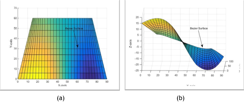
Figure 3. The final surface mesh in MATLAB program
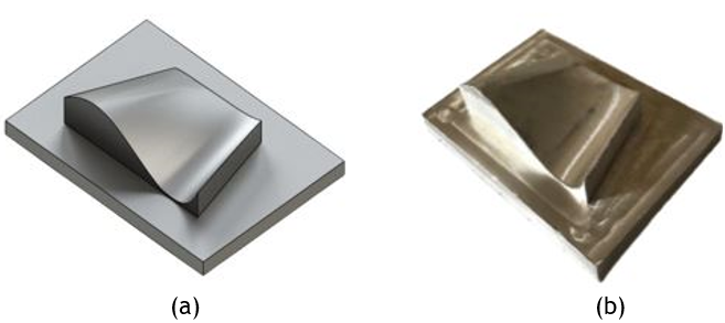
Figure 4. (a) A SOLIDWORKS die design and (b) final milling die
The Multi-Point Die
Sheet metal forming techniques are commonly used in the production and construction of various parts and components. While they share a common objective, each technique is built on distinct conceptual foundations and employs a unique set of tools and strategies. This section provides a comprehensive overview of the components involved in the implementation of the forming process using the suggested flexible MPD. In contrast to the conventional punch and die forming approach, the MPD technique replaces a single punch component with a collection of 121 adaptable pins.
The use of adaptable pins enables the creation of diverse shapes, reducing the need to produce a new punch for each individual product. The pins in question have a square cross-sectional area measuring 15 mm and a hemispherical shape with a radius of 7,5 mm at the ends. Their upper ends are equipped with a threaded hole measuring 8 mm in diameter and 40 mm in depth. Additionally, a cylindrical ring with a height of 2 mm and a radius of 5 mm is incorporated at the upper extremity to restrict the motion of the spring. High-carbon steel was chosen as the material for the pins. Top of Form
To eliminate the need for manual pin adjustment, a bolt is used to secure each pin to a spring. One end of the bolt is screwed into the pin, while the opposite end remains unattached and does not connect to any component. As a result, when a load is applied to the spring system, the pin undergoes a vertical displacement. The selected spring has a length of 80 mm and a radius of 6,5 mm. Based on the load-deformation curve from the compression test, the spring can withstand a maximum load of 236 N, resulting in a displacement of 44 mm. Hence, the calculated value of the spring stiffness is 5,36 N/mm. The 121 pins are arranged in a square configuration, forming an (11 x 11) matrix, and are located within an upper block measuring (280 x 280 x 15 mm). The block contains 121 holes with a radius of 4 mm for pin attachment, as well as four holes at the corners for guide placement. The guides have been specifically designed with a radius of 11 mm and a length of 270 mm. The lower section of the setup has four perforations at the corners, each with a radius of 11 mm. The configuration of the proposed MPD die is illustrated in figure 5. Notably, the MPD used in the forming process was manufactured by Khalida Kadim Mansor, a doctoral researcher associated with the Department of Production Engineering and Metallurgy at the University of Technology in Baghdad, Iraq.(14) The substitution of a single punch with a series of adaptable pins eliminates the need for producing a dedicated punch for each individual item. However, this approach does not include the production of the lower die. The lower die is custom-designed and requires production and integration with the MPD for each different product. The process of assembling the MPD with the bottom die is subject to certain constraints. The dimensions and configuration of the pins may affect the positioning of the lower die. Additionally, it is crucial that the dimensions of the die do not exceed the efficient forming region of the MPD. Conversely, utilizing a smaller die size is possible, resulting in partial activation of the pins during the forming process. The assembly of the MPD with the bottom die is illustrated in figure 6 using SOLIDWORKS design software and reality, respectively.

Figure 5. The final assembled MPD

Figure 6. The assembled MPD with the bottom die
Materials Selection
The selection of the product material and other key components is a crucial requirement for multi-point forming. The fin blank was chosen to be made of a brass alloy (Cu Zn 65-35) with a thickness of 0,71 mm. To mitigate the formation of dimples resulting from the presence of individual pins, elastomer with a 2 mm thick sheet and a hardness of 84 HA was employed in both the simulation and experimental work. The samples were cut to the same sizes as the brass plates, as shown in figure 7 (a, b, and c), illustrating the dimensions of the blank, the actual blank, and the rubber pad, respectively. Figure 8 (a, b, and c) illustrates the standard dimension of the tensile test spacemen according to ISO-6892 and the various stages of the brass material's tensile test, respectively. The results of tensile tests illustrate in tables 1 and 2 which provide a summary of the mechanical properties obtained through tensile testing of the brass plate and the rubber, respectively.

Figure 7. (a) The top view of the blank with its dimensions and (b) the actual blank (c) the rubber pad

Figure 8. Tensile test spacemen of Brass (65-35) in accordance with ISO-6892
|
Table 1. Mechanical properties of the brass 65-35 plate |
|||||
|
Material |
Ultimate Strength [MPa] |
Young’s Modulus [GPa] |
Poisson’s Ratio |
Yield Stress [MPa] |
Tangent Modulus [MPa] |
|
Brass (65-35) |
U |
E |
υ |
σy |
Et |
|
230 |
110 |
0,355 |
79 |
39 |
|
|
Table 2. Mechanical properties for the used elastic layer (rubber) |
|||
|
Material |
Yield stress [MPa] |
Young’s Modulus [MPa] |
Poisson’s Ratio |
|
Rubber |
10 |
25 |
0,48 |
Numerical Simulation
Computers have long been utilized to assist with various tasks due to their ability to perform complex operations quickly and accurately. For example, they can evaluate and analyze the qualities and attributes of a product or process. As a result, numerous strategies, methods, and concepts have been developed, with finite element analysis (FEA) being one of the most well-known. FEA can be conducted using various programs, and ANSYS-PC is recognized as one of the more powerful options.
MPF is a complex mechanical procedure that can be applied to various boundary conditions and non-linear shapes. In this work, the ANSYS 15.0 program is used to achieve numerical simulation under specific conditions. For instance, the element type Brick 8 node 185 is employed to create an explicit structural model and enhance computing performance. Furthermore, the entire 3D model of the fin shape is considered during the simulation process due to its complexity and lack of symmetry. To define the brass and rubber materials in ANSYS 15.0, typically it needs to specify their mechanical properties, as well as the hardness of the rubber, which was clarified in the material selection section. By utilizing node displacement to replicate the movement of the top pins, the changes in curvature between the intended surface and the actual product are examined. The boundary conditions, which are attached to the blank, enable the motion in the y-direction only with respect to the lower profile at a depth of (30) mm, and was immobilized by constraints in the x and z direction. The simulation includes three contact zones that need to be identified. The first contact represents the interaction between the rubber pad and the blank sheet (surface to surface/ flexible). While, the second contact represents the interaction between the upper pins and the elastic cushion (surface to surface/ rigid). Finally, the lower surface of the blank makes contact with the lower die (surface to surface/ rigid). The rubber and blank are chosen to have a friction coefficient of 0,02.
Two case studies were simulated to evaluate the effectiveness of the proposed solution in reducing wrinkles and dimples. In the first case, the upper pins, brass blank, and lower dies are in direct contact. In the second case, a piece of rubber is placed between the upper pins and the blank. The two case studies are illustrated in figure 9 (a and b), respectively.

Figure 9. (a) Case study 1 (direct contact) and (b) case study 2 (with adding rubber)
RESULTS
The present study utilizes numerical simulation to investigate an MPF process under two distinct cases: (i) direct contact and (ii) indirect contact facilitated by a rubber sheet. This section provides an analysis of the outcomes obtained from stress and strain diagrams for both cases. The distribution of Von Mises stress on the metal sheet after forming is depicted in figure 10 (a and b), with the latter figure showing the same distribution with the addition of a rubber sheet. The maximum Von Mises stress observed in the direct contact case is determined to be 0,155E+09. However, when incorporating the rubber, the maximum Von Mises stress is found to be lower, measuring at 0,113E+09. Furthermore, it can be observed that the yellow zone, which encompasses a significant portion of the surface area in the second case, exhibits a greater elevation compared to the first one. The use of rubber material facilitates the equitable distribution of force, enabling the upper pins to exert optimal pressure on the workpiece's surface.
Figure 11 (a and b) illustrates the two scenarios of direct and indirect contact in terms of strain distributions. The thickness reduction of the tough zone is greater in instances of direct contact compared to the utilization of rubber. As a result, the incorporation of a rubber sheet improves the distribution of strain. It is noteworthy that the use of rubber enhances the ultimate formability outcomes by yielding products with refined curved edges.
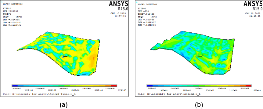
Figure 10. (a) The stress distribution of case study 1 and (b) the stress distribution case study 2

Figure 11. (a) The strain distribution of case study 1 and (b) the strain distribution case study 2
The formation of wrinkles and dimples is a significant issue observed in MPF procedures. The recognition of these phenomena in figures (10a) and (11a) can be achieved with a brief observation. The distance between the active points of the pins results in heightened stress concentration at these locations during the forming process. Additionally, the dimples exhibit a shape identical to that of the pins. However, the occurrence of dimples on the formed surface is not uniform in terms of visibility. This phenomenon can be attributed to the intricate and asymmetrical nature of the three-dimensional configuration, which requires a distinct displacement for each pin to achieve the ultimate shape. The precision of the curvature serves as an indicator of the excellence of the forming procedure, while substandard quality indicates the presence of the wrinkling anomaly. This phenomenon is also observable in figures (10a) and (11a). The utilization of a rubber sheet has resulted in a noteworthy decrease in both wrinkling and dimpling, as evidenced by figures (10b) and (11b). The presence of rubber aids in spreading the force, resulting in a notable decrease in the maximum stress and strain within the blank profile. In the second case, there is an approximately 27 % reduction in maximum stress and a 49 % reduction in strain.
Experimental Work

Figure 12. The MPF system in the press machine
After completing the simulation process and subsequent analysis, the findings of the second case study involving the application of rubber material between the pins and the plate produced favorable results. These included an acceptable final design, stress and strain evaluations, and the absence of dimples and wrinkles. Consequently, this approach was implemented in practical applications. The experimental process involved placing the system consisting of the MPD and the bottom die onto the Instron Tensile Instrument (model WDW - 200 E) press machine. The lower die was equipped with brass and rubber plates, which were affixed using a sponge. The sponge served to stabilize the plates without impacting the bending process. Figure 12 illustrates this system setup. Furthermore, the experimental setup used the same dimensions for the entire system as those employed in the numerical model.
The study employed two different punching velocities, specifically 5 and 15 mm/min, as input variables. These velocities were combined with different holding times of 1, 3, and 5 minutes. The required load for the forming process was 40 KN. As a result, products free of wrinkles or dimples were successfully created through the bending process, as indicated in figure 13.
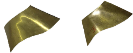
Figure 13. The final bending products
Dimensional Accuracy
Spring-back is a common occurrence in sheet metal forming processes and can affect various sheet metal parts, even the simplest ones. Different methods can be employed to evaluate the spring-back of complex shapes. Previous tests have been conducted to assess the dimensional precision of the final product. In this study, a 3D-Touch probe (802EW) was attached to an NC milling machine to measure the surface of the bent parts. Figure 14 illustrates the way the accuracy was tested.
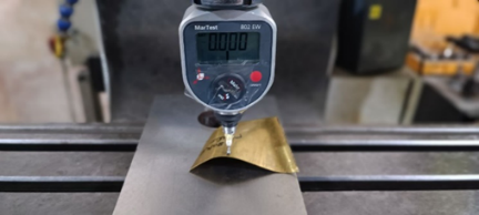
Figure 14. Accuracy test via NC milling machine
Analysis Results
The experiments were conducted using a rubber pad with blank material. Additionally, the dimensional accuracy of the shaped samples and the results obtained from simulation will be compared to the dimensions of the original die to evaluate the amount of spring-back and the degree of compliance of the products with the original die. The study investigated the effect of the forming speed and holding time on the dimensional accuracy of products formed by a multi-point die. Two different forming speeds were used in the study: 5 mm/min and 15 mm/min with holding times of approximately 1, 3, and 5 minutes. The difference between the points measured along the sample surface and the points of the original die was calculated. These results represent the spring-back of each point, and the average spring-back was calculated for each sample formed. The results show that the best results were achieved at a forming speed of 5 mm/min and a holding time of 5 minutes, resulting in a lower average spring-back (0,997). Furthermore, the results indicate that the use of rubber in the forming process yields optimal results, reducing metal stresses and strains, and eliminating surface defects such as dimples and wrinkles. By comparing the results obtained from the simulation process and practical experimentation with the original surface, the amount of spring-back can be calculated, as shown in table 3. Figure 15 illustrates a comparison of curvatures among three curves: the target shape, experimental shape, and simulation shape.
|
Table 3. The results obtained from the simulation process and practical experimentation with the original surface |
|||
|
Points |
Target shape |
Experimental shape |
Simulation shape |
|
0 |
0 |
0 |
7,2 |
|
9 |
6,79 |
6,4 |
9,8 |
|
18 |
9,95 |
9,8 |
9 |
|
27 |
8,94 |
9,4 |
5 |
|
36 |
4,49 |
5,6 |
-1,5 |
|
45 |
-1,8 |
-1,1 |
-6,8 |
|
54 |
-7,54 |
-6,1 |
-10,2 |
|
63 |
-12,23 |
-8,3 |
-10,3 |
|
72 |
-13,67 |
-8,6 |
-8,6 |
|
81 |
-11 |
-6,2 |
0 |
|
90 |
0 |
0 |
7,2 |

Figure 15. A comparison of curvatures among three curves: the target shape, experimental shape, and simulation shape
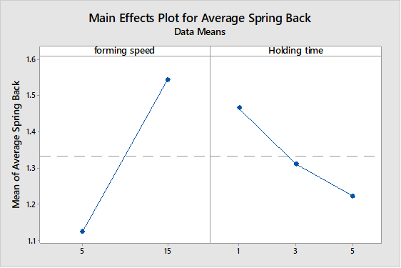
Figure 16. The relationship between process parameters and average spring back
The analysis of variance (ANOVA) was utilized for analyzing the results of the formed products using an orthogonal array, and the results indicate that the forming speed and holding time significantly affect the dimensional accuracy. ANOVA confirms the relationship between forming speed, holding time, and spring back, the relationship between process parameters and average spring back is shown in figure 16. The main graph for average spring back illustrates that as the forming speed increases, the average spring back also increases. This pattern is observed for the holding times as well. Furthermore, figure 17 (a and b) depicts the correlation between the forming speed and the holding time in relation to the mean spring back. In figure (17a) it can be observed that the lines are parallel, indicating the absence of any interaction between the forming speed and the holding time. Furthermore, the influence of the forming speed on the average spring back remains consistent across all levels of the holding time. However, from figure (17b), it is evident that the lines do not exhibit parallelism, suggesting the presence of an interaction between the forming speed and the holding time. The influence of the forming speed on the average spring back is contingent upon the duration of the holding time.

Figure 17. The relation between each process parameter with respect to the average spring
CONCLUSIONS
From the simulation and the experimental work the following conclusion is obtained and can be summarized as:
MPF is a significant sheet metal forming method that can produce simple and complex shapes, replacing the need for a special punch for each product, thus reducing manufacturing time and cost.
Manual adjustment of the pins in MPF may consume time and result in inaccurate results, and the shape and space of the pins can affect the quality of the formed surface. The use of springs attached to the pins allows for automatic adjustment of the pins, reducing setup time by up to 90 %.
Using ANSYS software for analysis and prediction of the MPF process is a recommended method, to analyze stresses and strains. As well as the estimated results closely match the experimental results.
Wrinkles and dimples on the final product in MPF can be treated by using appropriate elastic cushion types and thicknesses, and adding a sheet of rubber can improve stress and strain distributions.
The forming speed and holding time in MPF have a significant relationship with the average spring back of the products, as indicated by ANOVA results.
The study recommends a forming speed of 5 mm/min and a holding time of 5 minutes for achieving the minimum average spring back (0,997) in MPF.
Low forming speed (5 mm/min) yields better dimensional accuracy in MPF due to allowing enough time for material reorganization and reducing resistance to forming force.
Extended holding times in MPF result in a positive correlation with strain hardening and a decrease in spring-back magnitude.
REFERENCES
1. Dilip Kumar K, Appukuttan KK, Neelakantha VL, Naik PS. Experimental determination of spring back and thinning effect of aluminum sheet metal during L-bending operation. Mater Des 2014;56:613–9. https://doi.org/10.1016/j.matdes.2013.11.047.
2. Bachmann AL, Dickey MD, Lazarus N. Making light work of metal bending: Laser forming in rapid prototyping. Quantum Beam Sci 2020;4:14–7. https://doi.org/10.3390/qubs4040044.
3. Abbas TF, Younis KM, Mansor KK. The Influence of Process Parameters on Thickness Distribution in Multipoint Forming Process Using Finite Element Analysis. 2nd Int Conf Electr Commun Comput Power Control Eng ICECCPCE 2019 2019:120–5. https://doi.org/10.1109/ICECCPCE46549.2019.203759.
4. Li Y, Li R, Liang C, Liang J, Teng F. Influence of the Curvature of the Multipoint Die for Flexible Multipoint Stretch Bending on the Quality of Aluminum Profile. Math Probl Eng 2020;2020. https://doi.org/10.1155/2020/5960973.
5. Liu W, Chen YZ, Xu YC, Yuan SJ. Evaluation on dimpling and geometrical profile of curved surface shell by hydroforming with reconfigurable multipoint tool. Int J Adv Manuf Technol 2016;86:2175–85. https://doi.org/10.1007/s00170-015-8264-y.
6. Wardhani R, Putu S, Sanjoto BL, Nur H, Hari S. Numerical simulation of multipoint forming with circular die pins in hexagonal packing. Appl Mech Mater 2014;493:589–93. https://doi.org/10.4028/www.scientific.net/AMM.493.589.
7. Bedan AS, Algodi SJ, Hussain EA. Investigating the Effect of Hybrid Process: MPF/SPIF on the Microstructure and Mechanical Properties of Brass (65-35) Sheet. Adv Sci Technol Res J 2023;17:302–8. https://doi.org/10.12913/22998624/167409.
8. Abosaf M, Essa K, Alghawail A, Tolipov A, Su S, Pham D. Optimisation of multi-point forming process parameters. Int J Adv Manuf Technol 2017;92:1849–59. https://doi.org/10.1007/s00170-017-0155-y.
9. Selmi N, Salah HBH. Flexible multipoint hydroforming using metallic sheet medium. Second Tunis Congr … 2012:19–22. https://doi.org/10.13140/RG.2.1.2761.6889.
10. Paunoiu, V.; Maier, C.; Teodor, V.; Gavan E. Numerical Analysis of Multi-Point Forming Process. Int J Mod Manuf Technol 2011;III:85–90.
11. Liu Y, Li M, Ju F. Research on the process of flexible blank holder in multi-point forming for spherical surface parts. Int J Adv Manuf Technol 2017;89:2315–22. https://doi.org/10.1007/s00170-016-9198-8.
12. Lin X, Li Y, Cai Z, Liang J, Liang C, Yu K, et al. Effect of Flexible 3D Multipoint Stretch Bending Dies on the Shape Accuracy and the Optimal Design. Adv Mater Sci Eng 2018;2018. https://doi.org/10.1155/2018/1095398.
13. Qu E, Li M, Li R. Deformation behavior in multi-point forming using a strip steel pad. Proc Inst Mech Eng Part C J Mech Eng Sci 2020;234:1775–85. https://doi.org/10.1177/0954406219898233.
14. Abaas TF, Younis KM, Mansor K kadhim. Die Design of Flexible Multi-Point Forming Process. Al-Khwarizmi Eng J 2019;14:22–9. https://doi.org/10.22153/kej.2018.12.002.
FINANCING
The authors did not receive financing for the development of this research.
CONFLICT OF INTEREST
The authors declare that there is no conflict of interest.
AUTHORSHIP CONTRIBUTION
Conceptualization: Alyaa Al-Ghuraibawi, Aseel Hamad Abed, Khalida Kadhim Mansor.
Data curation: Alyaa Al-Ghuraibawi, Aseel Hamad Abed, Khalida Kadhim Mansor.
Formal analysis: Alyaa Al-Ghuraibawi, Aseel Hamad Abed, Khalida Kadhim Mansor.
Research: Alyaa Al-Ghuraibawi, Aseel Hamad Abed, Khalida Kadhim Mansor.
Methodology: Alyaa Al-Ghuraibawi, Aseel Hamad Abed, Khalida Kadhim Mansor.
Drafting - original draft: Alyaa Al-Ghuraibawi, Aseel Hamad Abed, Khalida Kadhim Mansor.
Writing - proofreading and editing: Alyaa Al-Ghuraibawi, Aseel Hamad Abed, Khalida Kadhim Mansor.
ANNEXES
Appendix A Part of MATLAB Bezier surface programming
PX1=[0 5 10 15;10 10 15 17;20 20 20 20;30 30 30 30];
PY1=[0 20 40 60;0 20 40 60;0 20 40 60;0 20 40 60];
PZ1=[15 10 6 1;19 14 8.5 1;22 19 7 1;15 12 5 -2];
I=1;
J=1;
for U=0:0.1:1;
for W=0:0.1:1;
U1=[U^3 U^2 U 1];
W1=[W^3 W^2 W 1];
M1=[-1 3 -3 1;3 -6 3 0;-3 3 0 0;1 0 0 0];
CX1(I,J)=U1*M1*PX1*M1'*W1';
CY1(I,J)=U1*M1*PY1*M1'*W1';
CZ1(I,J)=U1*M1*PZ1*M1'*W1';
I=I+1;
end
J=J+1;
I=1;
end
mesh(CX1,CY1,CZ1);
surf(CX1,CY1,CZ1);
hold on
% mesh(PX1,PY1,PZ1)
%%%%%%%%%%%%%%%%%%%%%%%%%%%%%%%%%%%%%%%%% 2
hold on