Category: STEM (Science, Technology, Engineering and Mathematics)
ORIGINAL
Structural behaviors of different corroded RC members strengthened by different types of concrete jackets
Comportamiento estructural de diferentes elementos de CR corroídos reforzados con diferentes tipos de recubrimientos de hormigón
Nada A. Mahmoud1 *, Yousif A. Mansoor1 *, Mahmoud K. Mohammed1 *
1Civil Engineering Department, University of Anbar, Ramadi, Iraq.
Cite as: Mahmoud NA, Mansoor YA, Mohammed MK. Structural behaviors of different corroded RC members strengthened by different types of concrete jackets. Salud, Ciencia y Tecnología - Serie de Conferencias. 2024; 3:831. https://doi.org/10.56294/sctconf2024831
Submitted: 24-01-2024 Revised: 05-04-2024 Accepted: 02-06-2024 Published: 03-06-2024
Editor: Dr.
William Castillo-González ![]()
Note: Paper presented at the 3rd Annual International Conference on Information & Sciences (AICIS‘23).
ABSTRACT
Existing corroded reinforced concrete (RC) structures must be repaired and strengthened to extend their service life. Otherwise, they must be demolished and rebuilt. In general, repair and strengthening are more cost-effective than demolition and reconstruction. This research assessed the performance of corrosion-damaged reinforced concrete beams and columns strengthened with different types of concrete. The corrosion rate of reinforcing columns and beams was assumed to be 10 % using accelerating electrochemical corrosion method. After steel corrosion, the surface of concrete members is roughened by sandblasting; it was then strengthened with different types of concrete: self-compacting concrete (SCC), fiber-reinforced self-compacting concrete (FRSCC), high-performance concrete (HPC), fiber-reinforced high-performance concrete (FRHPC), and fiber reinforced normal concrete (FRNC). Before and after corrosion, the flexural and compression tests were carried out for the beams and columns, respectively. Experimental findings demonstrated that the bearing and axial compression capacities of beams and columns were reduced considerably. due to the corrosion of reinforcements, and concrete jackets from different types of used concrete could efficiently restore the damage resulting from corroded steel rods. The study concludes that the use different types of concrete are suitable for the external strengthening of corroded RC members. However, for flexure, the strengthen concrete beam that achieved the highest increase in flexural and ductility is the one strengthens by 30 mm FRHPC jacket (8,65 %). For axial compression, strengthen concrete column that achieved the highest increase is that strengths with 30 mm of FRSCC (136,78 %).
Keywords: Self-Compacting Concrete; SCC; Fiber Reinforced Self Compacting Concrete; Corrosion; Strengthening; Concrete Jacket; High Performance Concrete.
RESUMEN
Las estructuras de hormigón armado corroídas deben repararse y reforzarse para prolongar su vida útil. En caso contrario, deben ser demolidas y reconstruidas. En general, la reparación y el refuerzo son más rentables que la demolición y la reconstrucción. Esta investigación evaluó el comportamiento de vigas y pilares de hormigón armado dañados por la corrosión y reforzados con diferentes tipos de hormigón. La tasa de corrosión de los pilares y vigas reforzados se supuso del 10 % utilizando el método de corrosión electroquímica acelerada. Tras la corrosión del acero, la superficie de los elementos de hormigón se desbastó mediante chorro de arena; a continuación, se reforzaron con diferentes tipos de hormigón: hormigón autocompactante (SCC), hormigón autocompactante reforzado con fibras (FRSCC), hormigón de altas prestaciones (HPC), hormigón de altas prestaciones reforzado con fibras (FRHPC) y hormigón normal reforzado con fibras (FRNC). Antes y después de la corrosión, se realizaron ensayos de flexión y compresión para las vigas y los pilares, respectivamente. Los resultados experimentales demostraron que las capacidades portante y de compresión axial de vigas y pilares se reducían considerablemente debido a la corrosión de las armaduras, y que las camisas de hormigón de diferentes tipos de hormigón utilizado podían restaurar eficazmente los daños resultantes de las varillas de acero corroídas. El estudio concluye que el uso de diferentes tipos de hormigón es adecuado para el refuerzo externo de elementos de CR corroídos. Sin embargo, para la flexión, la viga de hormigón reforzado que logró el mayor aumento en la flexión y la ductilidad es la reforzada por 30 mm de revestimiento FRHPC (8,65 %). Para compresión axial, la columna de hormigón armado que alcanzó el mayor incremento es la reforzada con 30 mm de FRSCC (136,78 %).
Palabras clave: Hormigón Autocompactante; HACC; Hormigón Autocompactante Reforzado con Fibras; Corrosión; Refuerzo; Camisa de Hormigón; Hormigón de Altas Prestaciones.
INTRODUCTION
Reinforced concrete (RC) structures are the most common structural systems in modern society because they are inexpensive to produce and maintain. However, environmental influences, design load, material qualities, structural design mistakes, and insufficient construction can all lead to a decline in the structural performance of RC members over time. One of the most common causes of deterioration in RC structures is reinforcement corrosion.(1,2)
Corrosion is represented by rust formation, which causes spalling and fractures in concrete cover and, consequently, decreases the structure’s load-bearing and axial compression capacities.(3) According to previous research, the corrosion of reinforcement bars decreases the bonding between the bars and the concrete, yield strength and ductility.(4) This can cause reductions in both service life and structural performance. Chloride and carbonation, which originate from the interaction between concrete elements and the atmospheric or adjacent environment, which includes sea water, de-icing solutions, and CO2 pollution, are the main influencing factors can cause steel corrosion.(5) Based on design considerations, Corroded and degraded concrete members have a much shorter service life than expected.(6,7)
Fayaad, T.S.(8) found that the ultimate load was considerably influenced by percentage of corrosion mass loss. Compared to a non-corroded reference concrete beam, the failure load decreased by approximately (14 % and 27 %) while 8,25 % and 14,15 % mass loss due to corrosion respectively. The accelerating corrosion process was exposed in this investigation for 5, 10, and 20 days. Due to the corrosion process, the bearing capacity decreases when the exposure duration to corrosion is increased in comparison to the reference beam without corrosion. In comparison to the control beam, the test results show that the ultimate loads reduce by 2,44, 11,1, and 16,0 % for corrosion periods of 5, 10, and 20 days.(9)
To extend the service life of existing structures, the reinforced concrete (RC) members must be repaired and reinforced; otherwise, the structure might be demolished and rebuilt. Generally, strengthening is more economical than demolition and reconstruction.(10) Existing techniques for strengthening reinforced concrete (RC) structures include:(11)
· Steel or fiber-reinforced polymer (FRP) reinforcement and/or strips installed on the surface.
· Steel plates with an external bond.
· High-strength FRP laminates installed over concrete.
Although it has been discovered that these techniques are effective at enhancing the strength of RC members, each has its drawbacks. The near-surface installation has negative effects on the nearby concrete. On concrete surfaces, externally bonded steel plates and FRP are at risk of debonding. Steel jackets also have a low corrosion resistance, decreasing demand for them.(12) In addition, fire resistance is low in externally attached FRP and emits toxic vapors during a fire.(13)
The first method for reinforcing concrete columns is concrete jacketing.(14) Lehman et al.(15) demonstrated the efficacy of repairing RC columns with concrete jacketing. The findings were, the RC-jacketed column exhibited greater rigidity and tensile strength than the original column. Strengthening corroded reinforced structures, particularly columns, is a practicable way to extend the duration of service for deteriorating structures.(16)
A common area of concrete research’ nowadays is strengthening preexisting RC beams, which can effectively increase the service lives. Haider A. Abdul Hameed in 2018 (17) used Fiber-reinforced self-consolidating concrete FRSCC to investigate restoring damaged concrete pillars. The results indicated that the enhanced FRSCC jackets are an effective restoration options with sufficient adhesiveness to precast concrete. As demonstrated by the results of the flexural tests, the fracture stress of the repaired beams might be greater due to the utilized concrete jacket in comparison to the control beams. The purpose of this increase is to make the damaged element or structure last longer in service. However, the purpose of this research was to assess the efficacy of polypropylene fiber PPF in SCC and optimized their volume fraction based on their fresh properties before employing it for strengthening.
The effect of concrete jacketing on rehabilitating damaged columns’ lateral load capability was studied by Bett et al.(18) When compared to the reference column, they discovered that the rehabilitated columns with a concrete jacket had increased stiffness and lateral load capacity.
SCC jackets were employed by Yuce et al.(19) to protect damaged columns from further collapse under continuous axial loads and cyclical lateral displacements. The SCC jackets increased the lateral stiffness of the authors’ damaged columns.
Using ultra-high performance fiber-reinforced concrete (UHPFRC) jackets, Dadvar, S.A. et al.(20) investigated the axial behavior of circular (RC) columns. Sandblasting was used to prepare the contact surfaces. The specimens were reinforced with 15 mm thick UHPFRC jackets containing steel fibers. They found that the bearing capacity of the strengthened sample increased by 131,3 % compared to the reference column.
Despite the extensive research that has been reviewed above, which conducted on uncorroded RC beams and columns strengthened with concrete jackets, concrete jacketing using different types of concrete has received little attention. The present investigation, in contrast, uses different types of concrete jackets made of SCC, FRSCC, HPC, FRHPC, and FRNC to strengthen square corrosion-damaged RC columns and beams. In addition, no studies have been found to study the effectiveness of these jackets on flexural and axial compression capacities of corrosion-damaged RC beams and columns simultaneously which have been studied extensively in the current work.
Experimental Program
Material properties
The normal concrete (NC), FRNC, SCC, FRSCC, HPC, and FRHPC were prepared using a combination of raw materials, including:
· Ordinary Portland Cement (OPC): Type I with 3,15 Specific gravity, and the initial and final setting times are 140 and 210 minutes, respectively. The features of this cement were precise to Iraqi requirements and Portland Cement Standard IQS NO. 5, 2019.(21)
· Fly ash (FA): with a 2,08 specific gravity and Blaine fineness of 380 m2/kg produced by (EUROBUILD COMPANY) was used. It mainly consists of 28 % alumina and 47,7 % silica. Class F may be used to describe this form of mineral filler In accordance with ASTM C 618, 2015.(22)
· Silica fume (SF): The United Arab Emirates (UAE) produced SF-Type Mega Add MS(D), which was used. In this investigation, the specific gravity of the silica particulate used was 2,2. According to ASTM C1240, it satisfies the specifications for silica fume.(23) (Table 1 shows the chemical compositions of C, FA and SF)
· Superplasticizer (SP): The third generation of Sika ViscoCrete -180 GS polycarboxylate polymer technology was used, a high range water reducing super plasticizing admixture with a 1,07 kg/ liter density and a pH value between 4 to 6. It satisfies all requirements of ASTM C-494 Types G.(24)
· Micro Steel Fibers (MSF): these were straight, 0,2mm in diameter and 15mm in length. With a minimum tensile strength of 2600 MPa, they were free of contamination and corrosion.
· Coarse aggregate (C.A): crashed C.A with a maximum size of 12mm and a specific gravity of 2,65. The test findings of this type of aggregate indicated that it met Iraqi specifications IQS NO. 45, 1984.(25)
· Fine aggregate (F.A): spherical F.A with a maximum size of 4,75mm, a bulk density of 2600 kg/m3 and a specific gravity of 2,62. This type was also identical to Iraqi specifications IQS NO. 45, 1984.(25)
|
Table 1. Chemical compositions of C, FA and SF |
|||||
|
Main oxides % |
Si |
Al2 O3 |
Cao |
Fe2 O3 |
L.O.I |
|
C |
20,06 |
4,80 |
62,95 |
3,35 |
2,30 |
|
FA |
47,68 |
27,73 |
5,11 |
18,32 |
3,71 |
|
SF |
94,2 |
0,3 |
0,2 |
0,82 |
3,36 |
NC and FRNC, in addition to the optimal fiber content in the FRSCC mixture, were produced through laboratory work. In contrast, the SCC, HPC, and FRHPC mixtures were produced in previous research (8,26,27) respectively. Table 2 provides each component’s mix proportions in kg/m3.
|
Table 2. Mix proportions in kg/m3 |
|||||||||
|
Concrete type |
w/b |
C |
C.A |
F. A |
W |
FA |
SF |
SP |
Steel fiber % |
|
NC |
0,51 |
365 |
1170 |
660 |
188 |
--- |
--- |
--- |
--- |
|
FRNC |
0,44 |
485 |
1210 |
850 |
215 |
--- |
--- |
11,8 |
0,25 |
|
SCC |
0,38 |
410 |
764 |
970 |
165 |
45 |
45 |
12,5 |
---- |
|
FRSCC |
0,38 |
410 |
764 |
970 |
165 |
45 |
45 |
12,5 |
0,47 |
|
HPC |
0,18 |
650 |
--- |
960 |
200 |
300 |
160 |
24,4 |
---- |
|
FRHPC |
0,18 |
650 |
--- |
960 |
200 |
300 |
160 |
24,4 |
0,77 |
Testing program and samples preparation
According to ASTM C39/C39M (28) and ASTM C469,(29) the compressive strength fc and modulus of elasticity Ec were evaluated respectively using cylindrical samples with dimensions of 150×300 mm. Prismatic samples with dimensions of 100×100×400 mm were used to test the flexural fr according to ASTM C78/C78M.(30) Cubes with dimension of 100mm were used to test the porosity P% and water absorption WA% according to ASTM C642.(31) As for splitting tensile strength ft, it was tested using cylindrical samples with dimensions of 100×200 mm according to ASTM C496/C496M.(32) Table 3 lists the characteristics of concrete mixtures.
|
Table 3. Mechanical properties of concrete mixtures as determined by testing |
||||||
|
Concrete type |
fc (MPa) |
ft (MPa) |
fr (MPa) |
Ec (GPa) |
P % |
WA% |
|
NC |
33 |
3,588 |
6,515 |
28,28 |
10,42 |
4,4 |
|
FRNC |
40,71 |
5,33 |
7,235 |
23,947 |
7,12 |
2,76 |
|
SCC |
49,5 |
3,98 |
6,831 |
30,24 |
3 |
1,197 |
|
FRSCC |
55,51 |
7,48 |
10,3 |
32,7 |
3,36 |
1,27 |
|
HPC |
53,56 |
4,32 |
5,66 |
16,56 |
5,44 |
2,46 |
|
HPFRC |
66,69 |
6,25 |
6,23 |
16 |
6,31 |
2,55 |
As for specimen preparation in this study, 14 concrete specimens were tested under different loading conditions, seven designed as beams and others as columns. The beams and columns were designed to be subjected to flexural and axial compression (crushing failure for short column) according to ACI 318-19 code.(33) The dimensions of beams and columns were 100×150×1200mm and 120×120×750mm, respectively. They were cast with normal concrete, with a compressive strength of 33 MPa. The thickness of the concrete cover was 20mm. All samples were longitudinally reinforced with bars of 10mm in diameter and yield strength of 539 MPa, while shear stirrups with a diameter of 6mm and yield strength of 458 MPa were used.
Details of the specimen are depicted in figure 1. Epoxy was utilized to secure each stirrup to prevent corrosion of these steel stirrups. At the connection point, the plastic tape was wrapped between the stirrups and longitudinal bars. As an electron acceptor’s source, the stripped wire twists all longitudinal bars exposed to corrosion.
Accelerating corrosion process
An electrochemical technique achieved a 10 % mass loss of steel reinforcement. A direct current DC was supplied to the longitudinal steel bars via an external power source. Before starting electrochemical corrosion, specimens were submerged for 24 hours, at a depth of approximately 140 mm from the bottom, in a 5 % NaCl salt solution to ensure that the environment surrounding and within the specimens remained saturated. The longitudinal steel bars that were inserted were linked electrically to the positive terminal of the DC power supply in order to function as anodes, as illustrated in figure 2. External stainless-steel plates that extend down the samples and are connected to the negative terminal of a voltmeter function as cathodes. The electrical circles were connected in series. Based on the surface area, a 2mA/cm2 current density has been applied to the embedding steel bars using the DC current source. As a theoretical guide, the time necessary to induce corrosion damage was computed using Faraday’s law (equation 1).(34,35,36,37,38)
m = I.T.s.a / n.F (1)
m = Mass losses (g), I = Current density (A/c), T = Period of corrosion (seconds), S = The area of the corroded bar’s surface (c), a = Atomic metal’s weight (56 g for Iron Fe+2), n = Iron’s electron number Fe → Fe+2 +2e- (n = 2 for Fe+2), F = The constant of Faraday (96500 C/mol)
Figure 1. Details regarding specimen reinforcement: (a) reinforcement details of reference beam (b) reinforcement details of reference column (c) A cross-sectional illustration of the reference beam (d) A cross-sectional illustration of the reference column
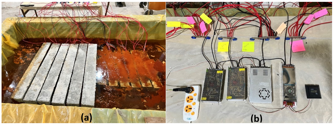
Figure 2. Accelerating corrosion process: a) corrosion in the samples; b) corrosion system
Specimen strengthening process
The main research variables were the type of structural member and the type of concrete used for strengthening, as shown in the table.4.
|
Table 4. Specimen ID of beams and columns |
|||
|
Spec. ID |
Beam |
Spec. ID |
Column |
|
BR |
Reference beam |
CR |
Reference column |
|
BC |
Corroded beam |
CC |
Corroded column |
|
BCS |
Corroded beam and strengthen with SCC |
CCS |
Corroded and strengthen with SCC |
|
BCH |
Corroded beam and strengthen with HPC |
CCH |
Corroded column and strengthen with HPC |
|
BCSF |
Corroded beam and strengthen with FRSCC |
CCSF |
Corroded column and strengthen with FRSCC |
|
BCHF |
Corroded beam and strengthen with HPFRC |
CCHF |
Corroded column and strengthen with HPFRC |
|
BCNF |
Corroded beam and strengthen with FRNC |
CCNF |
Corroded column and strengthen with FRNC |
Specimens were extracted from the electrochemically accelerated corrosion tank once the desired corrosion time had ended. After drying, the specimens to be strengthened are roughened by sandblasting process as shown in figure 3 a. Molds are made with new dimensions of 210×230×1200mm and 180×180×750mm for beams and columns respectively as shown in the same figure 3 d. The samples coated with a layer of epoxy to ensure the bond between the hardened concrete to the fresh one. The specimens were put inside the new molds and the fresh concrete were poured as jacket shown in figure 3 d. After 48 hours, they were placed in a water basin for curing up to 28 days. For columns, carbon fiber-reinforced polymer CFRP was used at both ends to ensure crushing failure as shown in figure 3 f.
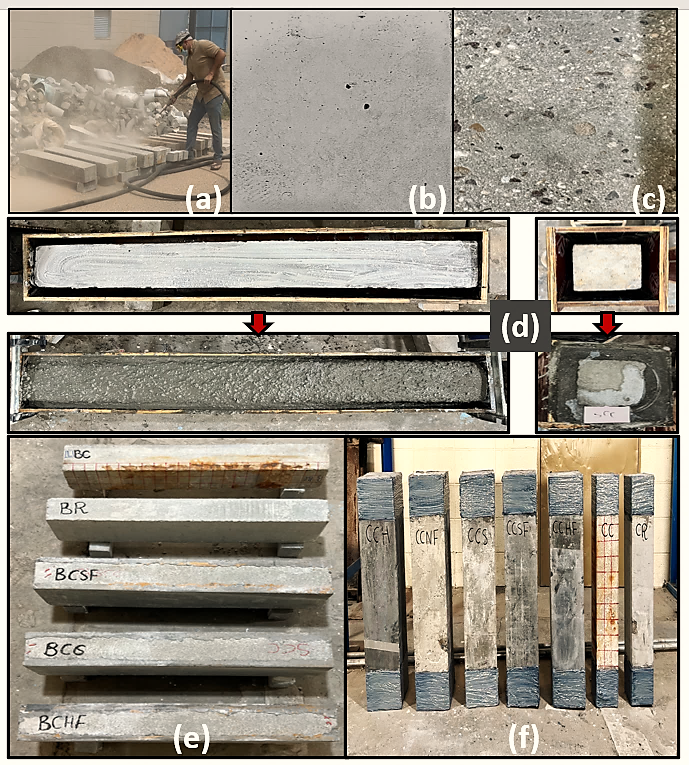
Figure 3. Specimens strengthening process: a) Sand blasting process; b) concrete surface before roughing; c) concrete surface after roughing; d) coating beams and columns with epoxy before casting concrete jacket; e) Reference, corroded and strengthen beams; f) Reference, corroded and strengthen columns.
Test setup and instrumentation
Figure 4 displays the test setup for the beam and column respectively. All the beam specimens were tested monotonically by a machine with a maximum capacity of 500 kN. They were supported with a clear span length of 1000 mm, and the plate with the two loading points was centered in the clear span with a distance of 150 mm between them. The load rate was 0,5 kN/s, and it was applied in load control mode. Beam transverse deflections were gauged using three linear variable differential transformers LVDTs: One at the midpoint of the span and the other at a distance of 200 mm from the supports. In contrast, the columns were tested under axial load machine at a rate of 0,5 kN/s and a maximal capacity of 2000 kN. Three LVDTs were used: one measuring the shortening of the columns, while the others at the center and the nearby bottom at a distance of 120 mm to measure the lateral deformation.
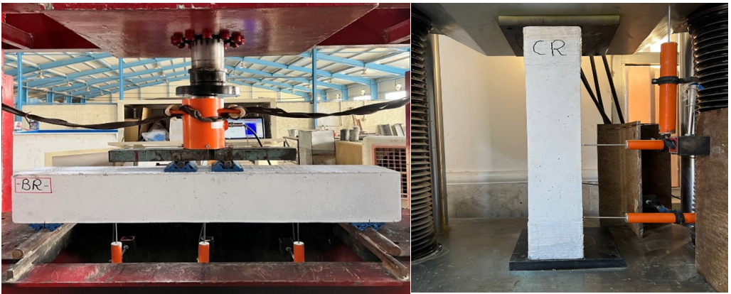
Figure 4. Test setup for beam and column
Measurement of actual corrosion ratio
The distractive technique assessed the mass losses of corroded longitudinal rebars after structural testing. The corroded rebars were extracted by breaking the corroded beams with hand-held electric percussion. Subsequently, the corroded steel bars underwent chemical cleansing by submerging them in a solution containing a high concentration of HCl acid. This process effectively eliminated rust and adhered concrete mortar according to ASTM G1-3.(34) Using a digital balance, the steel bars were weighed to ascertain the amount of steel loss (mass loss). The percentage of bar mass loss was computed using equation 2:
Mass loss % = Mass Before Corrosion (Kg) - Mass After Corrosion (Kg) / Mass Before Corrosion (Kg) * 100 % (2)
RESULTS AND DISCUSSION
The behavior of R.C beams
Table 5 provides a summary of the experimental setup test results for the following: mass losses of tensile longitudinal bars of corroded beams, corrosion mass loss, load at the first flexural crack (Pcr), ultimate load (Pu), change percent in Pu to BR, and deflection at ultimate load (Δu). Furthermore, reported is the maximum crack width that was measured for the larger crack present on the face of the beam during failure.
|
Table 5. The experimental test results for beams |
||||||
|
Beam ID |
Corr. mass loss (%) |
Ultimate Load (Pu) (KN) |
Load at First crack (pcr) (KN) |
Change percent in Pu with respect to BR |
Def. @ ultimate load (Δu) |
Max. crack width at failure (mm) |
|
BR |
- |
100 |
25 |
Ref. |
17,65 |
3,5 |
|
BC |
10,045 |
90,58 |
25 |
-9,42 |
16,17 |
6,7 |
|
BCS |
9,66 |
101,88 |
30 |
+1,88 |
20,75 |
20 |
|
BCSF |
8,21 |
108,56 |
40 |
+8,56 |
19,7 |
20 |
|
BCH |
8,66 |
100 |
25 |
0 |
19,93 |
21 |
|
BCHF |
8,24 |
108,56 |
35 |
+8,56 |
24,23 |
20 |
|
BCNF |
9,12 |
104,43 |
35 |
+4,43 |
21,84 |
28 |
From the second column of the table 5, its clear that the actual corrosion rates are close to the theoretical ones. This indicates the validity of using Faraday’s law estimate the age needed to obtain 10 % corrosion rate. The third column of the table represents the ultimate load which blotted in figure 5 and the differences between the obtained values will be discussed later on in the next paragraph. It’s seen that there was no change in the load at the first crack of the corroded beam without strengthening compared to the reference beam, and the same is true for the BCH beam (corroded beam strengthened by high performance concrete jacket). This unchanged might be due to lower modulus of rupture of high-performance concrete (see Table 3). As for the rest of the strengthened beams, it’s noted that there was an increase in the load at the first crack and the highest increase in those that contain fibers because the possible delay in the appearance of cracks of fiber reinforced jacket. From observing column 7 of the table, there was an increase in the width of the crack in the corroded beam without strengthening and this might be due to damage in concrete caused by the corrosion process. As for the strengthened beams, it was noted a significant increase in the width of the crack due to the increase in the thickness of the concrete layer below the reinforcement steel. Although the increase in the crack width, a significant increase in the bearing capacity of the strengthened beams was recorded as shown in figure 5.
The effect of strengthening techniques on restoring the stiffness of corroded beams has been thoroughly investigated by comparing the load-deflection relationship curves of the tested beams, as shown in figure 5.
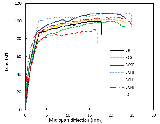
Figure 5. Load-deflection curves of the reinforced concrete beam
From figure 5, it can be seen that there were three intervals: i) When the beam is in the elastic stage, the curves start as straight lines. ii) the second interval starts when the deflection grows fast with a slight increase in the applied stress until failure, and iii) the visual cracks cause the curve to transform to a nonlinear form with a changing slope. As a consequence of corrosion damage, the results indicate that the peak load for beam BC decreased by approximately 9,42 %, with a corrosion mass loss percentage of 10,045 %, in comparison to beam BR. At the same time, the value of deflection at the midspan for ultimate loads was reduced by 8,4 % compared to the control beam. Mahmood and Lateef (9), Fayaad et al.(39) and Triantafyllou et al.(40) were the researchers whose access to these findings was closed. The experimental results demonstrated that the corroded RC beam had a less ductile failure mode than a control beam at the same age.
As for the strengthened beams, the results showed that all types of concrete jackets improved resistance in varying proportions. In addition, the failure was more ductile than the control and corroded beams. Beams BCS and BCH restored their resistance to the reference beam BR without an effective increase. This might be due use the jackets without any fibers. In contrast, the rest of the beams exceeded the resistance of the reference beam by percentages of 4,43 % and 8,56 % respectively. This shows the role of fibers in increasing the efficiency of jackets for strengthening and this finding is in line with those obtained by Yishuo Huang et al.(41)
Figure 6 shows failure modes and cracks for all tested beams, which shows that all beams failed with flexural failure.
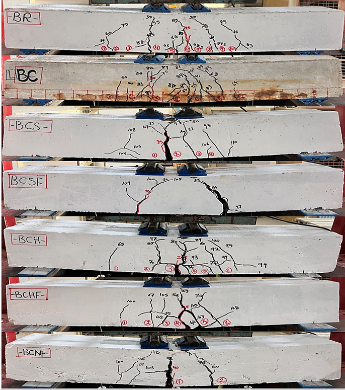
Figure 6. Modes of cracking in RC beams using different types of concrete
For all beams, the first visible fracture appeared close to the beam’s bending zone as a consequence of tensile stresses might be exceed the concrete’s tensile strength. On the other hand, perpendicular cracks first appeared on the tension the region under the sample’s neutral axis. As the loading progressed, these cracks grew increasingly complicated as they spread and interacted.
Compression behavior of columns
Figure 7 shows the load-shortening curves for all tested columns.
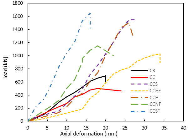
Figure 7. Load-Shortening curves of RC columns
The results in figure 7 show a significant decrease in the axial compression capacity of the corroded column compared to the reference column by about 28 %, which agrees with the results obtained by Xiongfei Liu et al.(42) The reason for this decrease might be due to the decrease in the area of reinforcing steel and the cracks resulting from the corrosion process on the concrete. As for the strengthened columns, the results demonstrated that all types of concrete jackets improved resistance in differing proportions and this might be attributed to the increase in cross section area (loading area). However, 30mm FRSCC jacket achieved the highest resistance for the CCSF column which was 136,78 % higher than the control column and less deformation of 16mm compared to 20 mm deformation in control column. On the other hand, the lowest resistance and highest deformation were recorded for the CCHF column (47,77 % and 34mm respectively). However, the latter showed better performance than the control column. The actual mass losses of the corroded columns, ultimate Loads (Pu), change percent in Pu to CR, and ultimate axial deformation are listed in Table 6. It should be highlighted here that the ultimate loads and ultimate deformation are obtained from figure 7.
|
Table 6. The experimental test results for columns |
||||
|
Column ID |
Corrosion mass loss (%) |
Ultimate Load (Pu) (KN) |
Change percent in Pu with respect to CR |
Ultimate axial deformation |
|
CR |
- |
694,5 |
Ref. |
20 |
|
CC |
11 |
501 |
-27,86 |
18 |
|
CCS |
10,5 |
1548,9 |
+123,02 |
26 |
|
CCSF |
10,2 |
1644,5 |
+136,78 |
16 |
|
CCH |
10,12 |
1504 |
+116,55 |
26 |
|
CCHF |
10 |
1026,3 |
+47,77 |
34 |
|
CCNF |
9,72 |
1150,3 |
+65,63 |
18 |
With regard to the mass losses in table 6, they were also closed to the theoretical value. However, they were closer to the theoretical value than those obtained from corroded beams. The possible reason for this difference is the shorter length of steel reinforcement used in columns. Figure 8 shows the failure modes of tested columns.
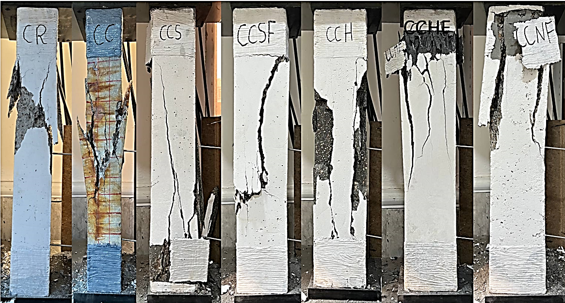
Figure 8. Modes of cracking in RC columns using different types of concrete
It is noted that the failure of columns CR and CC is a crushing failure, which is what happens to short columns. The RC columns have been loaded to the point of failure. As a result, the longitudinal reinforcing bars were bent in some samples. Because CFRP was used at both ends of each specimen, the failure zones were relocated to the middle, which ultimately caused the longitudinal reinforcing bars to bend.
The form of failure was different in the strengthened columns, and the CFRP failed in transferring the load to the center, and overall rupture occurred in the columns CCS, CCHF, and CCNF. Crushed concrete can be observed at the sides. In CCSF and CCH columns, failure occurs between CFRP regions, while CCH is characterized by separating large pieces of concrete from the original column. In contrast, with the failure in the CCSF column, no separation of concrete pieces occurs.
CONCLUSIONS
Based on the experimental work conducted for this study, the following can be concluded:
· Corrosion of steel reinforcements significantly reduced the bearing and axial compression capacities of beams and columns.
· As ccompared to the BR beam (without corrosion), the ultimate bearing load decreased by 9,42 % due to corrosion.
· As compared to the CR column (without corrosion), the axial compression capacity decreased by 27,86 % due to corrosion.
· As compared to control beam BR, strengthening by 30mm HPC jacket restored the beam to its strength before corrosion.
· Using 30mm SCC jacket showed a slight increase in beam strength by 1,88 %.
· The highest bearing capacity (8,56 % higher than control beam BR) were achieved in the BCHF beam (corrosion-damaged strengths by 30mm FRHPC jacket) with delay in appearance of the first crack.
· The axial load-carrying capacities of all strengthen RC columns improved significantly due to the use of different types of concrete jackets.
· The highest axial compression capacity (136,78 % higher than control column CR) was achieved in CCSF column (Retrofitted column strengths by 30mm FRSCC jacket).
· Strengthening beams and columns using different types of concrete jackets can be considered as an effective way to retrofit corroded columns and beams exposed to 10 % mass loss.
REFERENCES
1. K. Andisheh, et al., Influence of chloride corrosion on the effective mechanical properties of steel reinforcement. Structure and Infrastructure Engineering, 2019. 15(8): p. 1036-1048.
2. Z. Yu, et al., Accelerated simulation of chloride ingress into concrete under drying–wetting alternation condition chloride environment. Construction and Building Materials, 2015. 93: p. 205-213.
3. J. Broomfield, Corrosion of steel in concrete: understanding, investigation and repair. 2003, CRC Press.
4. C. Fang, et al., Bond behaviour of corroded reinforcing steel bars in concrete. Cement and concrete research, 2006. 36(10): p. 1931-1938.
5. J.-S. Jung, B.Y. Lee, and K.-S. Lee, Experimental study on the structural performance degradation of corrosion-damaged reinforced concrete beams. Advances in Civil Engineering, 2019. 2019: p. 1-14.
6. H. Baji, W. Yang, and C.-Q. Li, Optimal FRP-strengthening strategy for corrosion-affected reinforced concrete columns. Structure and Infrastructure Engineering, 2018. 14(12): p. 1586-1597.
7. M.M. Kashani, J. Maddocks, and E.A. Dizaj, Residual capacity of corroded reinforced concrete bridge components: State-of-the-art review. Journal of Bridge Engineering, 2019. 24(7): p. 03119001.
8. T.S. Fayaad, Strengthening of Corroded Reinforced Concrete Beams by SCC Using Different Strengthening Configurations, 2022, Anbar.
9. N.K. Mahmood, and A.M. Lateef, Effect of corrosion longitudinal steel bars on the flexural strength of RC beams. Tikrit Journal of Engineering Sciences, 2021. 28(2): p. 44-53.
10. M. Nishino, and T. Aoki, Nonlinear analysis and damage monitoring of a one-sided patch repair with delamination. Composite structures, 2006. 73(4): p. 423-431.
11. S.S. Zhang, T. Yu, and G. Chen, Reinforced concrete beams strengthened in flexure with near-surface mounted (NSM) CFRP strips: Current status and research needs. Composites Part B: Engineering, 2017. 131: p. 30-42.
12. A. Committee, Guide for the design and construction of externally bonded FRP systems for strengthening concrete structures (ACI 440.2 R-17). American Concrete Institute, Farmington Hills, MI, 2017.
13. F. Yuan, M. Chen, and J. Pan, Flexural strengthening of reinforced concrete beams with high-strength steel wire and engineered cementitious composites. Construction and Building Materials, 2020. 254: p. 119284.
14. C.-K. Ma, et al., Repair and rehabilitation of concrete structures using confinement: A review. Construction and Building Materials, 2017. 133: p. 502-515.
15. D.E. Lehman, et al., Repair of earthquake-damaged bridge columns. Structural Journal, 2001. 98(2): p. 233-242.
16. S. Raza, et al., Strengthening and repair of reinforced concrete columns by jacketing: State-of-the-art review. Sustainability, 2019. 11(11): p. 3208.
17. H.A. Abdulhameed, H. Nassif, and K.H. Khayat, Use of fiber-reinforced self-consolidating concrete to enhance serviceability performance of damaged beams. Transportation Research Record, 2018. 2672(27): p. 45-55.
18. B.J. Bett, R.E. Klingner, and J.O. Jirsa, Lateral load response of strengthened and repaired reinforced concrete columns. Structural Journal, 1988. 85(5): p. 499-508.
19. H.F. Karadogan, Local thin jacketing for the retrofitting of reinforced concrete columns. Struct Eng Mech, 2007. 27(5): p. 589-607.
20. S.A. Dadvar, D. Mostofinejad, and H. Bahmani, Strengthening of RC columns by ultra-high performance fiber reinforced concrete (UHPFRC) jacketing. Construction and Building Materials, 2020. 235: p. 117485.
21. IQS, Iraqi specification for Portland Cement requirements. 2019.
22. A. Standard, C618-15 Standard Specification for Coal Fly Ash and Raw or Calcined Natural Pozzolan for Use in Concrete. ASTM International: West Conshohocken, PA, USA, 2015.
23. C. ASTM, C 1240-2005 Standard specification for silica fume used in cementitious mixtures. in American Society for Testing and Materials.
24. D.H.-R.W.-R., Admixture, ASTM C 494, Type F or Type G. Products: Subject to compliance with requirements, products which may be incorporated in the Work include, but are not limited to, the following.
25. 45, I.N., The Used Aggregate from Natural Sources in Concrete and Building. 1984.
26. D.A. Suleman, M.K. Mohammed, and Y.A. Mansoor, Iraqi Journal of Civil Engineering.
27. D. Suleman, M.K. Mohammed, and Y.A. Mansoor, Optimization of different properties of ultra-high performance concrete mixes for strengthening purposes. Iraqi Journal of Civil Engineering, 2022. 15(2): p. 72-85.
28. A. Standard, ASTM C39/C39M–20 Standard Test Method for Compressive Strength of cylindrical Concrete Specimens. West Conshohocken, PA, 2020.
29. A.C. 469, ASTM C469/C469M-14: Standard Test method for static modulus of elasticity and poisson’s ratio of concrete in compression. Annual Book of ASTM Standards, 2014.
30. A. ASTM, C78/C78M-18 Standard Test Method for Flexural Strength of Concrete Using Simple Beam with Third-Point Loading. West Conshohocken: ASTM International, 2018.
31. Y. Bu, R. Spragg, and W. Weiss, Comparison of the pore volume in concrete as determined using ASTM C642 and vacuum saturation. Advances in Civil Engineering Materials, 2014. 3(1): p. 308-315.
32. A. ASTM, C496/C496M-11 Standard Test Method for Splitting Tensile Strength of Cylindrical Concrete Specimens, ASTM International, West Conshohocken, PA, 2004, 2011.
33. A. 318-19, Building Code Requirements for Structural Concrete (ACI 318-19) and Commentary, 2019, ACI Committee 318, Farmington Hills, MI, USA.
34. B. Almassri, et al., Behaviour of corroded shear-critical reinforced concrete beams repaired with NSM CFRP rods. Composite structures, 2015. 123: p. 204-215.
35. H.S. Attar, M.R. Esfahani, and A. Ramezani. Experimental investigation of flexural and shear strengthening of RC beams using fiber-reinforced self-consolidating concrete jackets. in Structures. 2020. Elsevier.
36. B. Hu, et al., Experimental and theoretical investigation on the hybrid CFRP-ECC flexural strengthening of RC beams with corroded longitudinal reinforcement. Engineering Structures, 2019. 200: p. 109717.
37. M. Sahmaran, et al., Effect of corrosion on shear behavior of reinforced engineered cementitious composite beams. ACI structural journal, 2015. 112(6).
38. Z. Ye, W. Zhang, and X. Gu, Deterioration of shear behavior of corroded reinforced concrete beams. Engineering Structures, 2018. 168: p. 708-720.
39. M.K. Mohammed, Y.A. Mansoor, and T.S. Fayaad, The effect of Corroded Longitudinal Steel Bars on Flexural Behavior of Reinforced Concrete Beams. Anbar Journal of Engineering Sciences, 2022. 13(2).
40. G.G. Triantafyllou, T.C. Rousakis, and A.I. Karabinis, Effect of patch repair and strengthening with EBR and NSM CFRP laminates for RC beams with low, medium and heavy corrosion. Composites Part B: Engineering, 2018. 133: p. 101-111.
41. Y. Huang, et al., Reinforced concrete beams retrofitted with UHPC or CFRP. Case Studies in Construction Materials, 2022. 17: p. e01507.
42. X. Liu, and Y. Li, Static bearing capacity of partially corrosion-damaged reinforced concrete structures strengthened with PET FRP composites. Construction and Building Materials, 2019. 211: p. 33-43.
FINANCING
None.
CONFLICT OF INTEREST
None.
AUTHORSHIP CONTRIBUTION
Conceptualization: Nada A. Mahmoud, Yousif A. Mansoor, Mahmoud K. Mohammed.
Research: Nada A. Mahmoud, Yousif A. Mansoor, Mahmoud K. Mohammed.
Writing - original draft: Nada A. Mahmoud, Yousif A. Mansoor, Mahmoud K. Mohammed.
Writing - revision and editing: Nada A. Mahmoud, Yousif A. Mansoor, Mahmoud K. Mohammed.